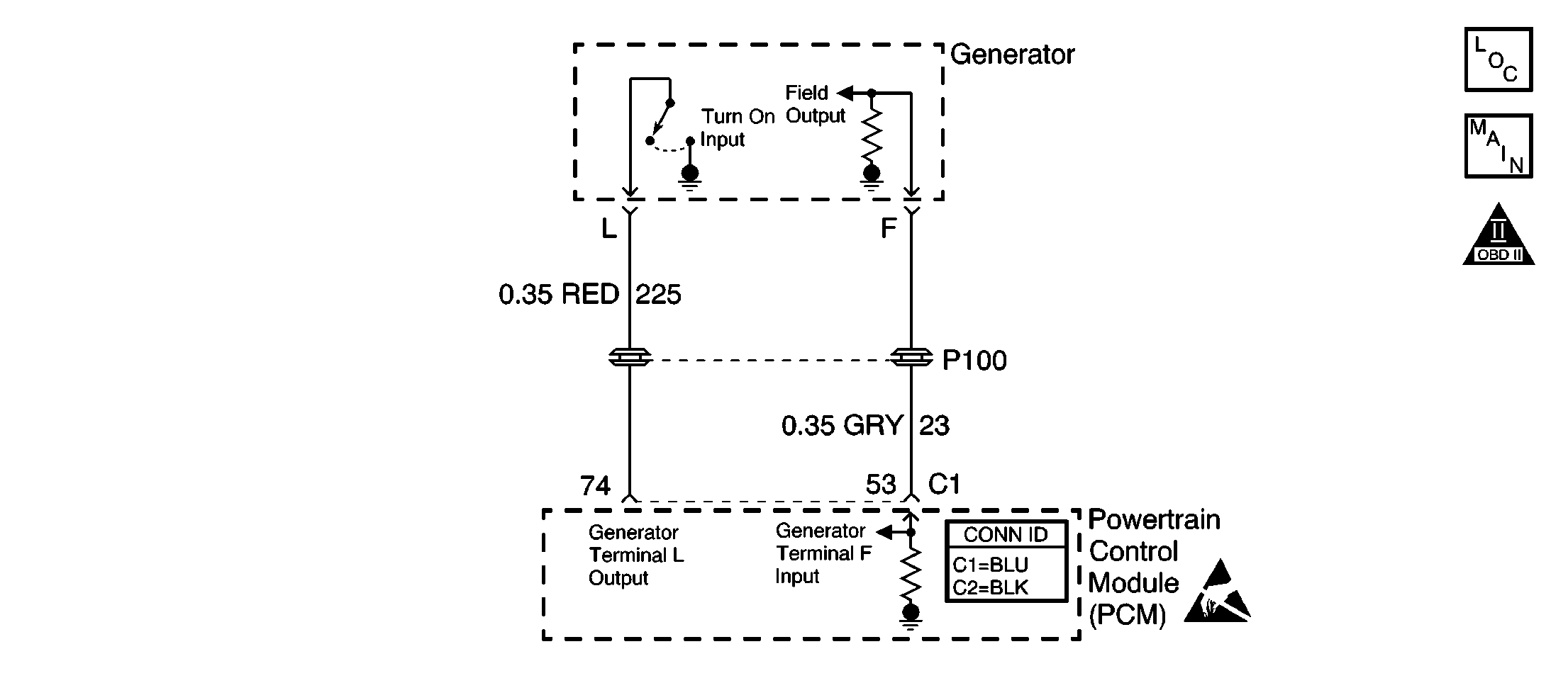
Circuit Description
The generator communicates to the Powertrain Control Module (PCM) over 2 lines, the L, or lamp, circuit and the F, or field, circuit. The PCM uses the L circuit to monitor faults in the charging system. The F circuit is used by the PCM to monitor the duty cycle of the generator. The PCM will adjust the idle speed according to the generator load.
Diagnosis
Use the following diagnostic table to diagnose the generator F and L circuits.
Use the following scan tool parameters when diagnosing the PCM controlled generator.
Generator PWM - Range 0-100%: The generator F terminal is a pulse width modulated (PWM) duty cycle or load input to the PCM from the generator. As the generator load increases, the PCM can sense the change and adjust the idle speed accordingly.Generator L Terminal - Range Inactive/Active: The generator L terminal indicates whether the PCM is allowing the generator to operate. The PCM can disable the generator under certain conditions in order to ease starting. Active indicates that the PCM is allowing generator operation, while inactive indicates that the PCM is not allowing generator operation.
Diagnostic Aids
| • | A Body Control Module (BCM) DTC may set when a generator malfunction is present. Inspect for any BCM DTCs and make any necessary repairs. |
| • | When the engine is not running, the generator duty cycle will be displayed above 5 percent. If the generator duty cycle reads 0 percent, then the field circuit is either open or shorted to ground. |
| • | An intermittent problem may be caused by the following conditions: |
| • | A poor connection |
| • | A rubbed-through wire insulation |
| • | A broken wire inside the insulation |
| • | Any circuitry, that is suspected as causing the intermittent complaint, should be thoroughly checked for the following items: |
| - | Any incorrect mating |
| - | Any broken locks |
| - | Any poor terminal to wiring connections |
| - | Any physical damage to the wiring harness |
Test Description
The number below refers to the step number on the diagnostic table.
Step | Action | Values | Yes | No |
|---|---|---|---|---|
1 | Did you perform the Powertrain On-Board Diagnostic (OBD) System Check? | -- | Go To Step 2 | |
2 | Does the scan tool indicate that the generator PWM is within the indicated range? | 5% - 95% | Go To Diagnostic System Check - Engine Electrical in Engine Electrical. | Go to Step 3 |
3 |
Use a scan tool in order to command the generator on while monitoring the DMM. Does the voltage change from the first indicated value to the second indicated value? | 0 V 5 V | Go To Step 4 | Go to Step 5 |
4 |
Does the reading change? | -- | Go to Diagnostic System Check - Instrument Cluster in Instrument Panel, Gauges, and Console | Go to Step 7 |
5 |
Did you find and correct the condition? | -- | Go To Step 11 | Go to Step 6 |
6 |
Did you find and correct the condition? | -- | Go To Step 11 | Go to Step 9 |
7 |
Did you find and correct the condition? | -- | Go To Step 11 | Go to Step 8 |
8 | Test the (F) circuit for an open or short to ground.
Did you find and correct the condition? | -- | Go To Step 11 | Go to Step 9 |
9 |
Did you find and correct the condition? | -- | Go To Step 11 | Go to Step 10 |
|
Important:: The replacement PCM must be programmed. Refer to Powertrain Control Module Replacement/Programming . Replace the PCM. Refer to Powertrain Control Module Replacement . Did you complete the repair? | -- | Go To Step 11 | -- | |
11 |
Does the DTC reset? | -- | Go To Step 2 | System OK |
