Removal Procedure
Notice: Handle the oxygen sensors carefully in order to prevent damage to the component. Keep the electrical connector and the exhaust inlet end free of contaminants. Do not use cleaning solvents on the sensor. Do not drop or mishandle the sensor.
Important:
• Bank 2 on the LC3 engine is the left side of the engine while sitting in the driver seat. • Sensor 2 is the second sensor down stream from the engine towards the rear of the vehicle. • A special anti-seize compound is used on the oxygen sensor threads. New service sensors should already have the compound applied to the threads. Coat the threads of a reused sensor with anti-seize compound P/N 5613695 or equivalent.
- Remove the engine sight shield. Refer to Intake Manifold Sight Shield Replacement.
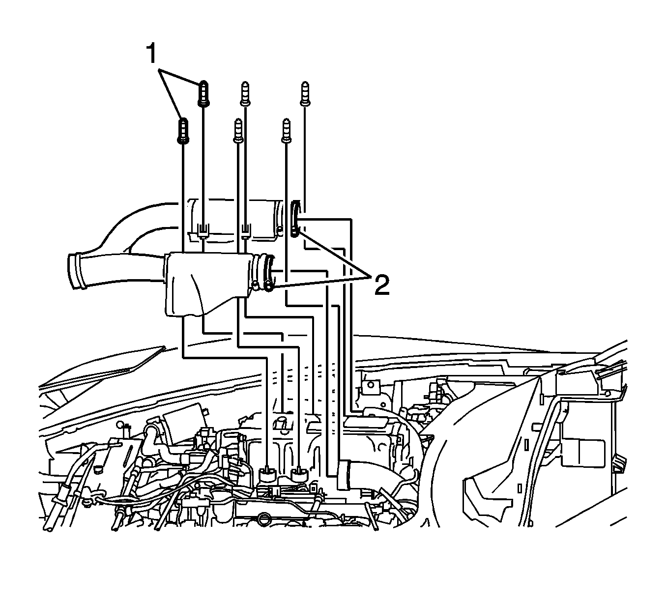
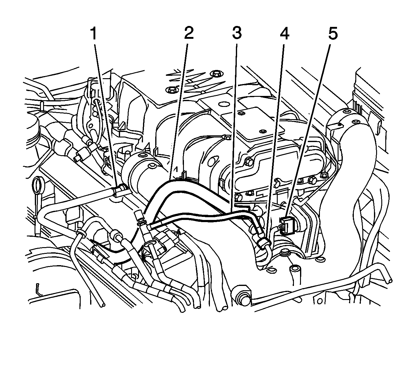
- Remove the ball studs (1), loosen the duct clamps (2) and remove the front section of the supercharger inlet duct assembly. Refer to Supercharger Inlet Duct Assembly Replacement .
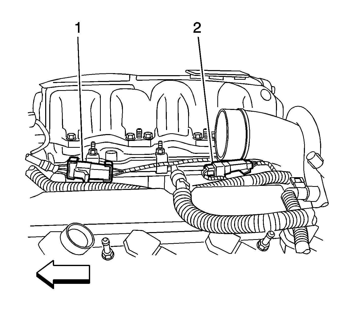
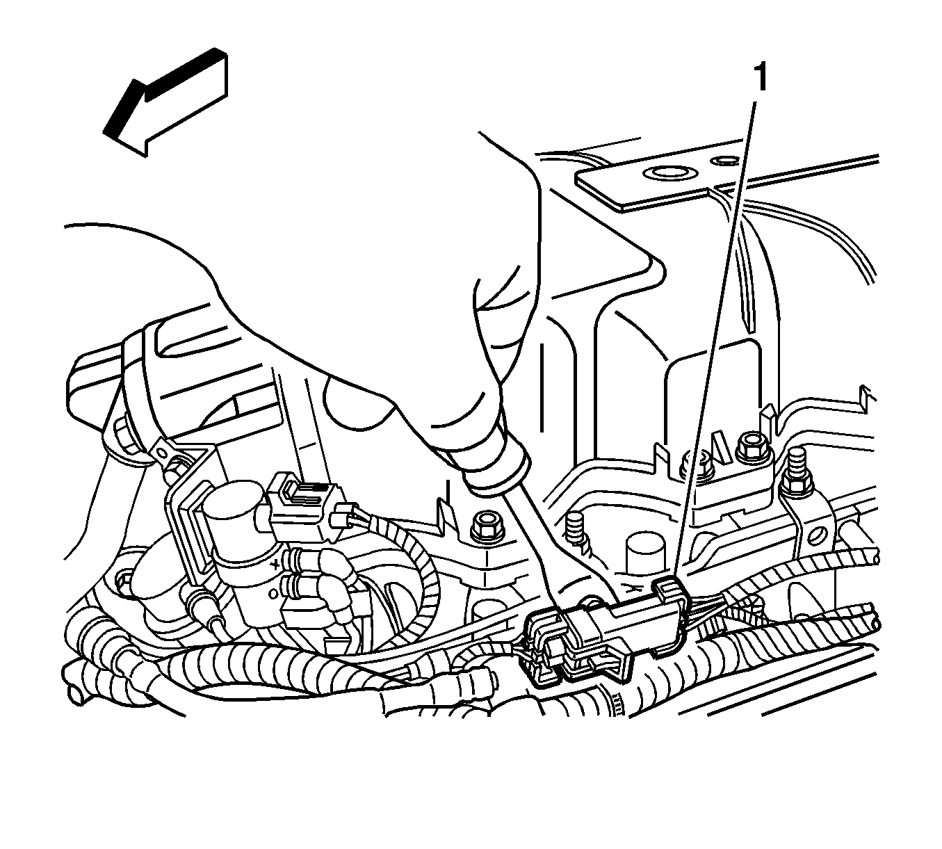
- Separate the bank 2, sensor 1 electrical connector assembly (1) from the fuel rail bracket.
- Disconnect the oxygen sensor electrical connector from the engine wiring harness connector.
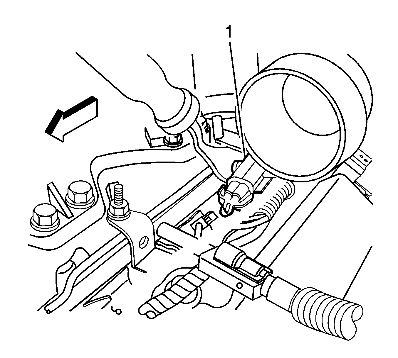
- Separate the bank 2, sensor 2 electrical connector assembly (1) from the fuel rail bracket.
- Disconnect the oxygen sensor electrical connector from the engine wiring harness connector.
- Attach a suitable length of mechanics wire to the bank 2, sensor 2 oxygen sensor electrical connector.
- Disconnect the evaporative emission (EVAP) hose (3) from the chassis bundle at the front of dash. Position the hose aside.
- Disconnect the brake booster hose and check valve from the brake booster. Position the hose aside.
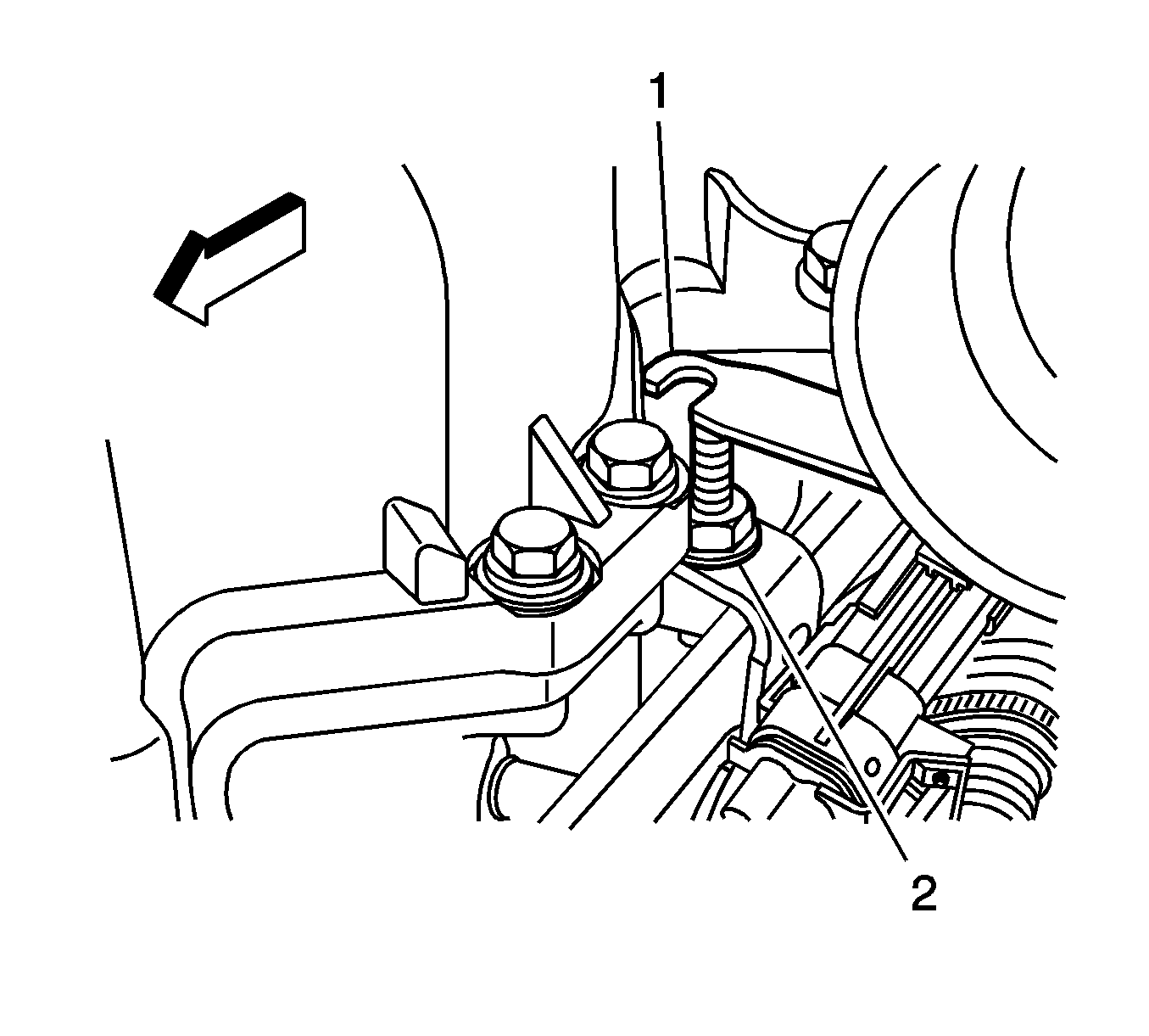
- Reposition the rear inlet duct upward. Place the inlet duct bracket (1) on top of the mounting stud (2).
- Remove both oxygen sensor electrical connectors and wires from under the rear section of the supercharger inlet duct.
- Raise and support the vehicle. Refer to Lifting and Jacking the Vehicle .
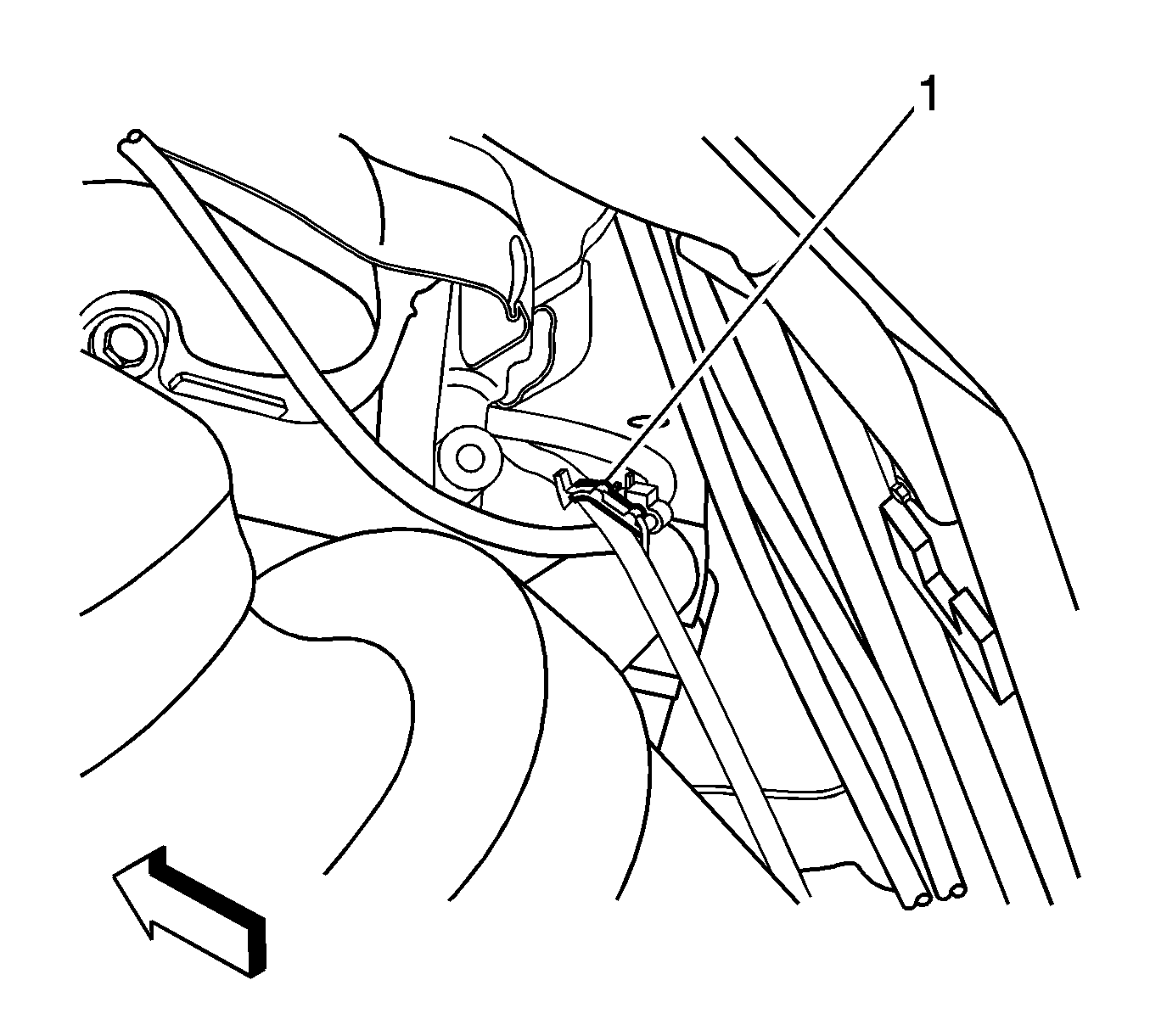
- Remove the oxygen sensor wire harnesses from the retainer (1) at the rear of the engine.
- Note the wire routing for reassembly.
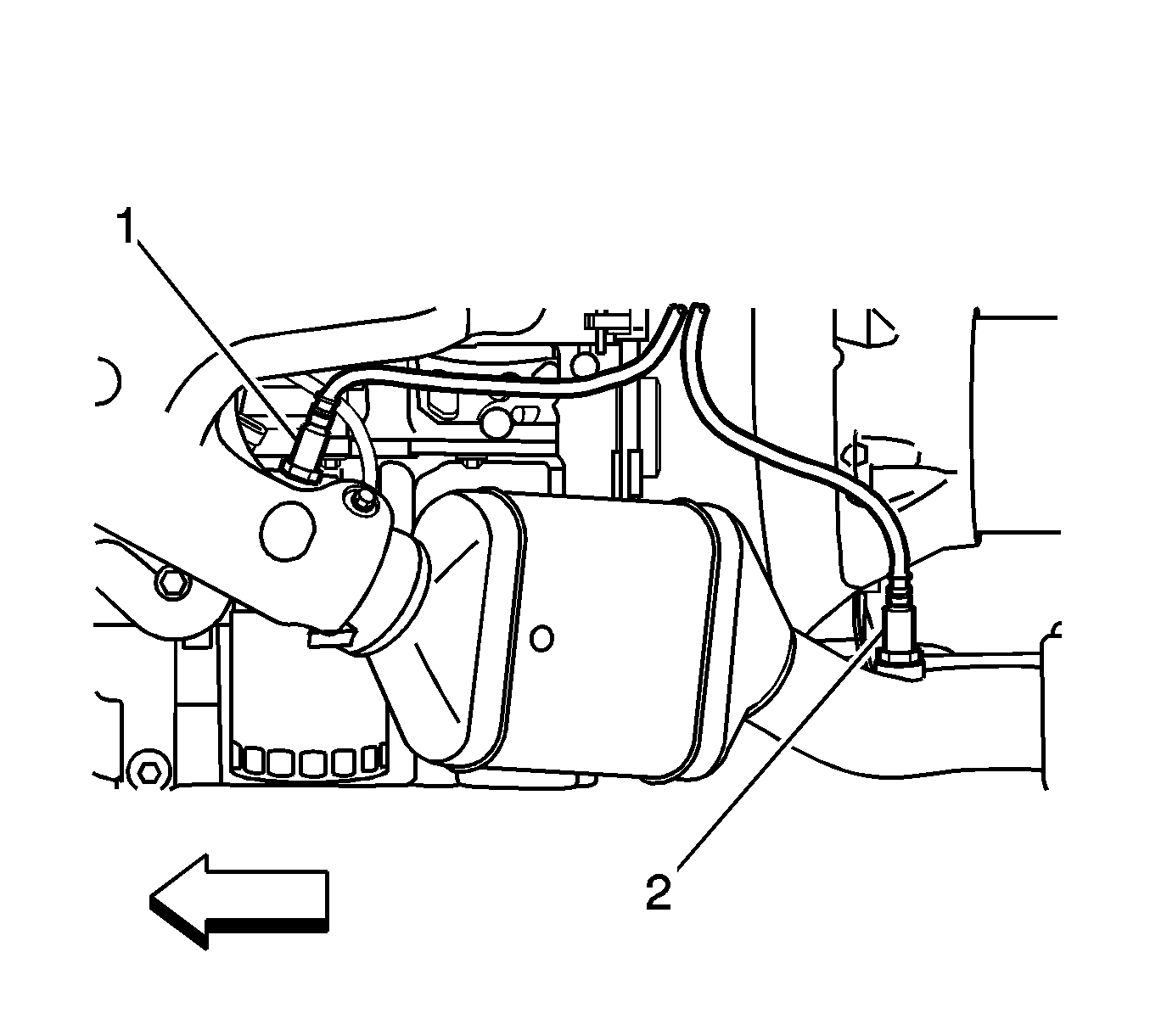
- Gently pull the bank 2 sensor 2 oxygen sensor (2) wire harness and connector down from the engine compartment.
- Remove the mechanics wire from the electrical connector.
- Remove the bank 2 sensor 2 oxygen sensor (2) from the exhaust manifold.
Important: Disconnect the positive crankcase ventilation (PCV) fitting from under the front of the supercharger inlet duct during inlet duct removal.
Installation Procedure
- Install the bank 2 sensor 2 oxygen sensor (2) to the exhaust manifold.
- Attach the mechanics wire to the oxygen sensor electrical connector.
- Lower the vehicle.
- Using the mechanics wire, pull the exhaust sensor electrical connector and wire harness upward to the engine compartment.
- Route both oxygen sensor electrical connectors and wires under the rear section of the supercharger inlet duct.
- Install the electrical connector retainer to the electrical connector.
- Connect both oxygen sensor electrical connectors to the engine wiring harness connectors.
- Install both oxygen sensor electrical connector assemblies (1,2) to the fuel rail brackets.
- Place the rear inlet duct to the installed position.
- Connect the brake booster hose and check valve to the brake booster.
- Connect the evaporative emission (EVAP) hose (3) to the chassis bundle at the front of dash.
- Raise and support the vehicle. Refer to Lifting and Jacking the Vehicle .
- Install the oxygen sensor wire harnesses to the retainer (1) at the rear of the engine. Ensure that the wire harnesses are secure and away from hot exhaust components.
- Lower the vehicle.
- Install the front section of the supercharger inlet duct assembly. Tighten the duct clamps (2) and secure the duct assembly with the ball studs (1). Refer to Supercharger Inlet Duct Assembly Replacement .
- Install the engine sight shield. Refer to Intake Manifold Sight Shield Replacement .
Notice: Use the correct fastener in the correct location. Replacement fasteners must be the correct part number for that application. Fasteners requiring replacement or fasteners requiring the use of thread locking compound or sealant are identified in the service procedure. Do not use paints, lubricants, or corrosion inhibitors on fasteners or fastener joint surfaces unless specified. These coatings affect fastener torque and joint clamping force and may damage the fastener. Use the correct tightening sequence and specifications when installing fasteners in order to avoid damage to parts and systems.

Tighten
Tighten the heated oxygen sensor (HO2S) to 42 N·m (31 lb ft).
