Tools Required
J39765-A
Fuel Sender Lock Ring Tool
Removal Procedure

- Disconnect the negative battery cable. Refer to
Battery Negative Cable Disconnection and Connection
.
- Remove the right fuel tank. Refer to
Fuel Tank Replacement - Right Side
.
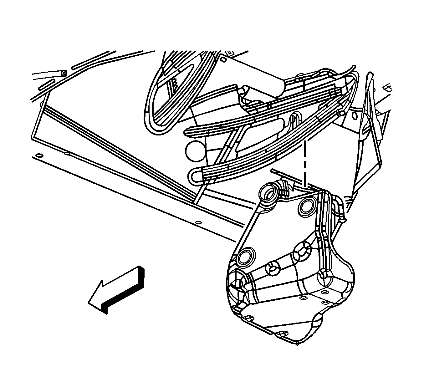
- Place the fuel tank on a suitable work surface.

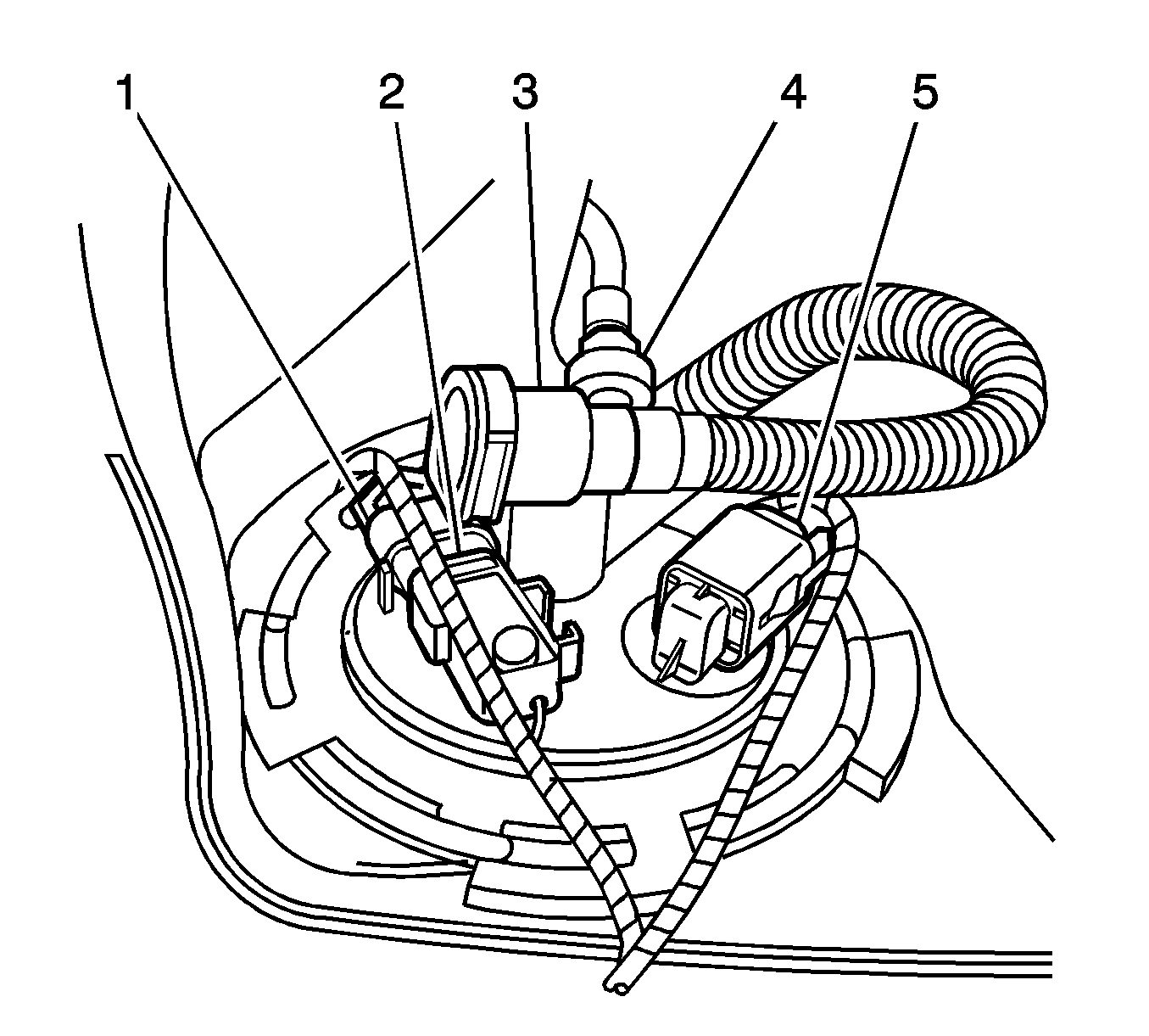
- Disconnect the evaporative emissions (EVAP) purge line (4) from the fuel tank module.
- Disconnect the fuel tank module harness connector (5).
- Disconnect the fuel tank pressure (FTP) sensor harness connector (1).
- If replacing the fuel tank module, remove the FTP sensor (2). Refer to
Fuel Tank Pressure Sensor Replacement
.

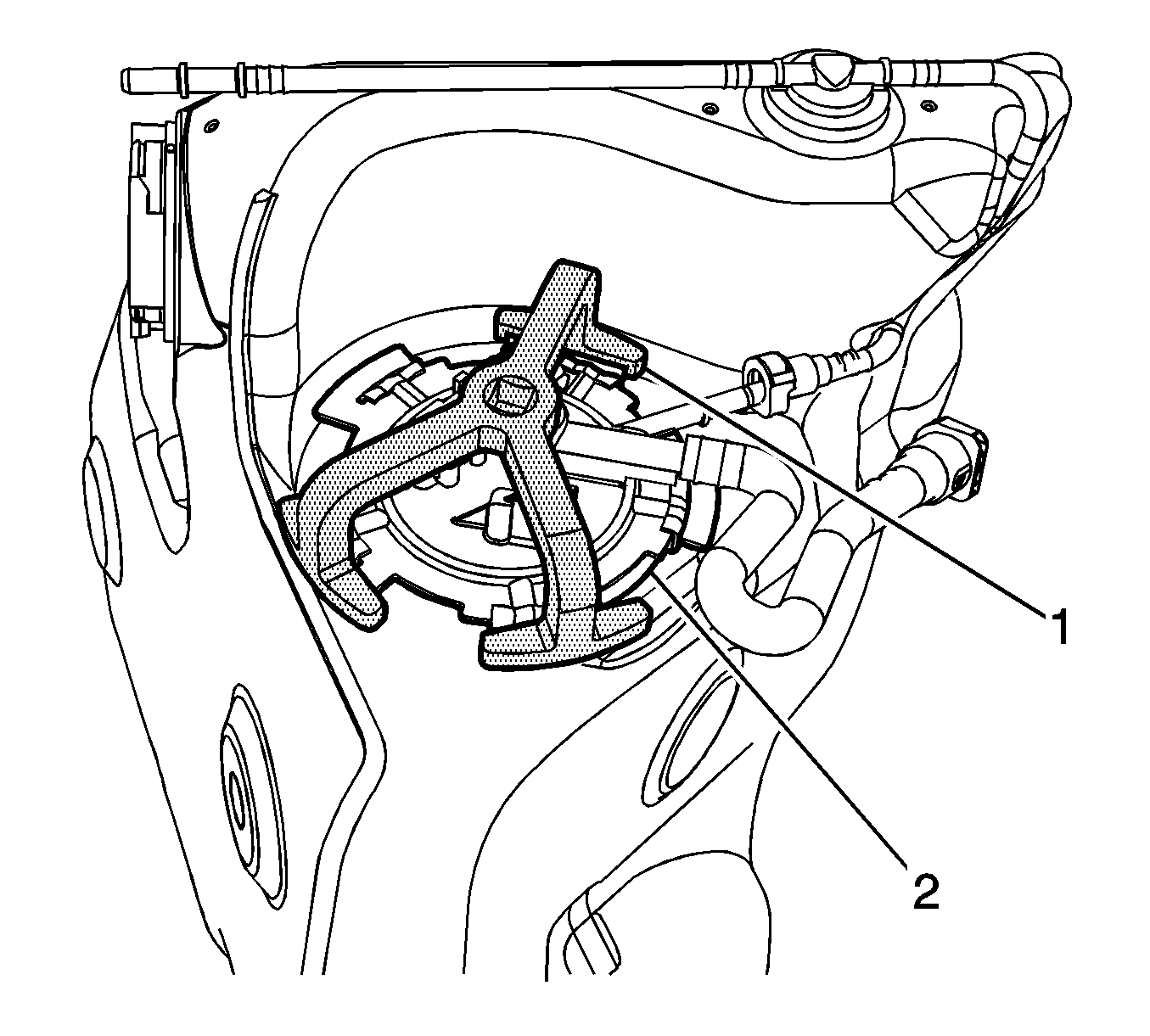
Important: The fuel tank module is spring loaded and will spring upward when the locking ring is removed.
- Using the
J39765-A
(1), remove the fuel tank module locking ring (2), by rotating the
J39765-A
in a counterclockwise direction.

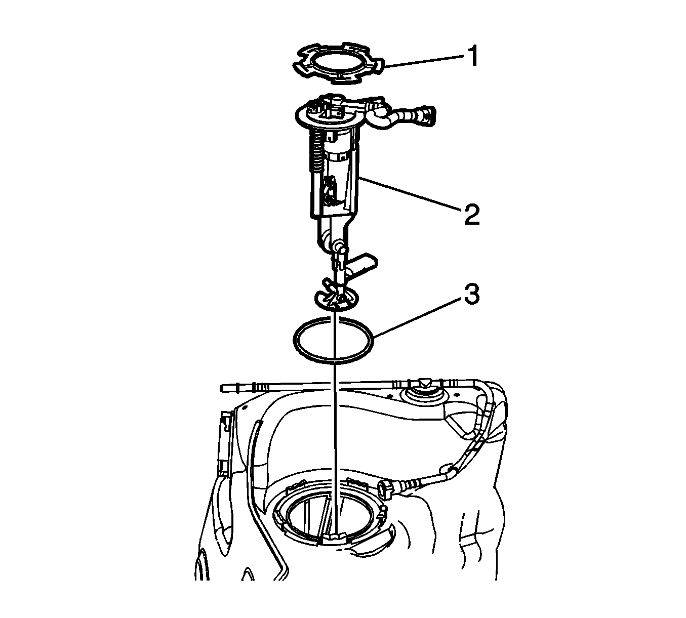
- Carefully remove the fuel tank module (2) from the fuel tank half way with the jet lines connected. Ensure not to damage the
fuel level float arm.
- Disconnect the internal fuel line quick-connect fittings from the fuel tank module ports, noting the location of the lines for installation.
- Remove the fuel tank module from the fuel tank using care not to damage the fuel level float arm.
- Remove the fuel tank module O-ring (3) from the fuel tank opening.
Installation Procedure

- Install a NEW fuel tank module O-ring (3) to the fuel tank opening.
Important: Pull on each internal fuel line to ensure that the quick-connect fittings are secure.
- Pull the internal fuel lines up through the fuel tank module opening and connect the internal fuel line quick-connect fittings to the fuel tank module ports in the location noted during disassembly.
- Install the fuel tank module lock ring (1) into position on the fuel tank module.
- Install the fuel tank module into the fuel tank, using care not to damage the fuel level sensor arm.
- Compress and align the fuel tank module.

- Using the
J39765-A
(1), fully lock the fuel tank module lock ring (2) in place, by rotating the
J39765-A
in
a clockwise direction.
- Using a digital multi-meter, verify the full and empty readings resistance reading of the fuel tank module. Turn the fuel tank upside down to achieve the full tank reading.
Resistance
| • | Empty 40 ohms resistance |
| • | Full 250 ohms resistance |

- Install the FTP sensor (2), if previously removed. Refer to
Fuel Tank Pressure Sensor Replacement
.
- Connect the FTP sensor harness connector (1).
- Connect the fuel tank module harness connector (5).
- Connect the EVAP purge line (4) to the fuel tank module.

- Install the right fuel tank. Refer to
Fuel Tank Replacement - Right Side
.
- Connect the negative battery cable. Refer to
Battery Negative Cable Disconnection and Connection
.
- Perform the following procedure in order to test for leaks:
| 14.1. | Turn ON the ignition switch, for 2 seconds. |
| 14.2. | Turn OFF the ignition, for 10 seconds. |
| 14.3. | Turn ON the ignition. |
| 14.4. | Inspect for fuel leaks. |
- Program the transmitters. Refer to
Transmitter Programming
.


