GM Service Manual Online
For 1990-2009 cars only
Makes
🢒
Cadillac
🢒
2004
🢒
XLR
🢒
Accessories
🢒
Entertainment
🢒 Body Control System Schematics
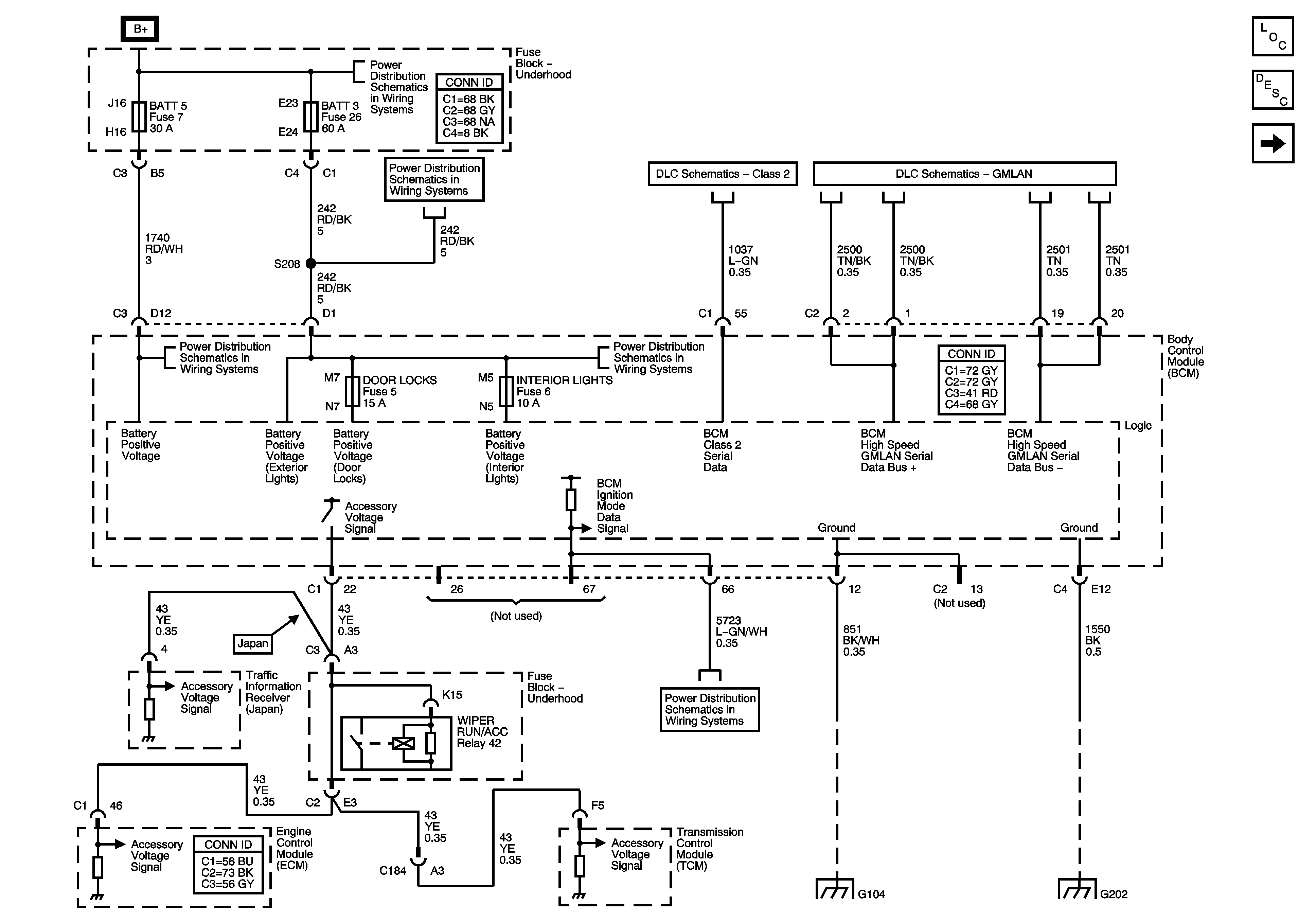
Figure
1:
DLC, Ground and Power
Master Electrical Component List
Body Control System Description and Operation
Lighting References 1 of 2
Fuse Block-Underhood Bussing
Fuse Block-Underhood Fuses; BATT3 and STOP/B/U/LPS, BCM Fuses; BTSI SOL/COL LOCK, PWR FLDG MIR-EXT/RET, RADIO/ANT/VICS, REAR FOG/ALDL TOP SW, and REVERSE LAMPS
Class 2
GMLAN
Fuse Block-Underhood Fuse: BATT5, BCM Fuses; ACCA/DRIV DR SW, IGNITION SW/INTR SENS, ONSTAR, PARK BRAKE SOL A, and TILT/TELE SW/MEM SEAT MOD
BCM Fuses; A.C.LATCH/PK BRK B, CLUSTER, DOOR LOCKS, HVAC/PWR SND, INTERIOR LIGHTS, ISRVM/HVAC, and TUTD SW/STRG COL SW
Ignition Modes
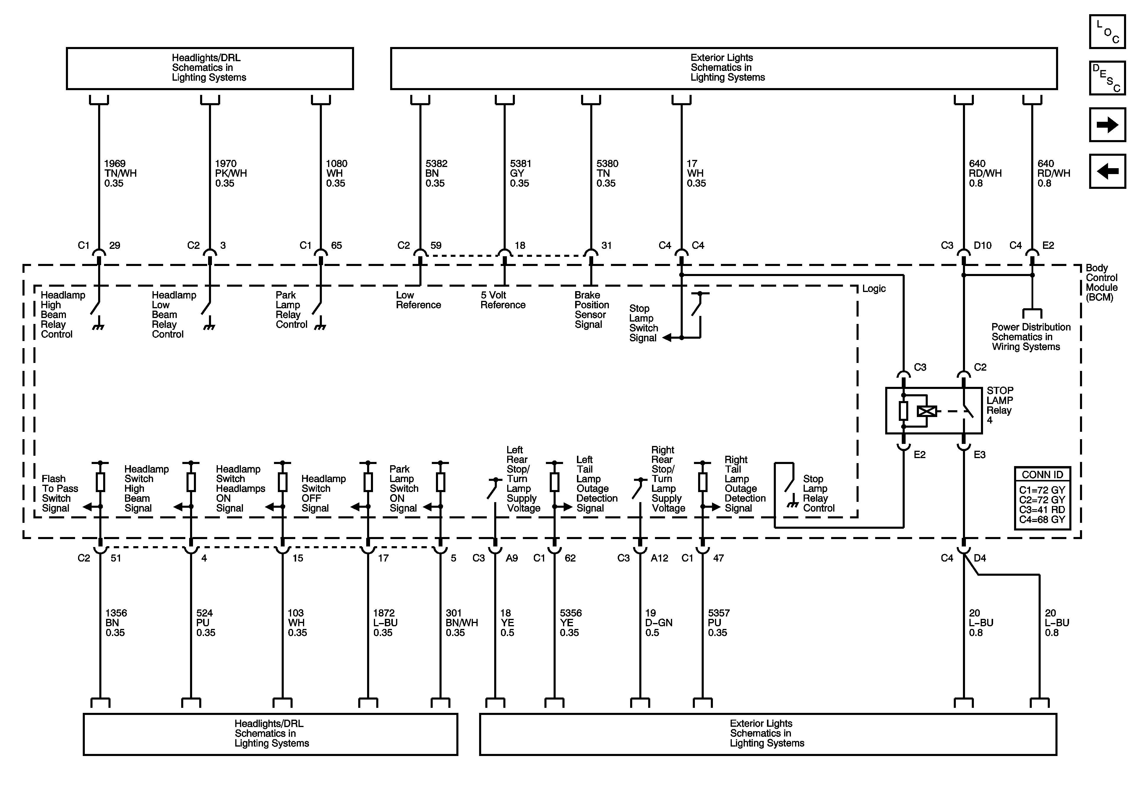
Figure
2:
Lighting References - 1 of 2
Master Electrical Component List
Body Control System Description and Operation
Lighting References 2 of 2
DLC, Ground and Power
Headlamp/DRL Controls
Stoplamps
Fuse Block-Underhood Fuses; BATT3 and STOP/B/U/LPS, BCM Fuses; BTSI SOL/COL LOCK, PWR FLDG MIR-EXT/RET, RADIO/ANT/VICS, REAR FOG/ALDL TOP SW, and REVERSE LAMPS
Headlamp/DRL Controls
Stoplamps
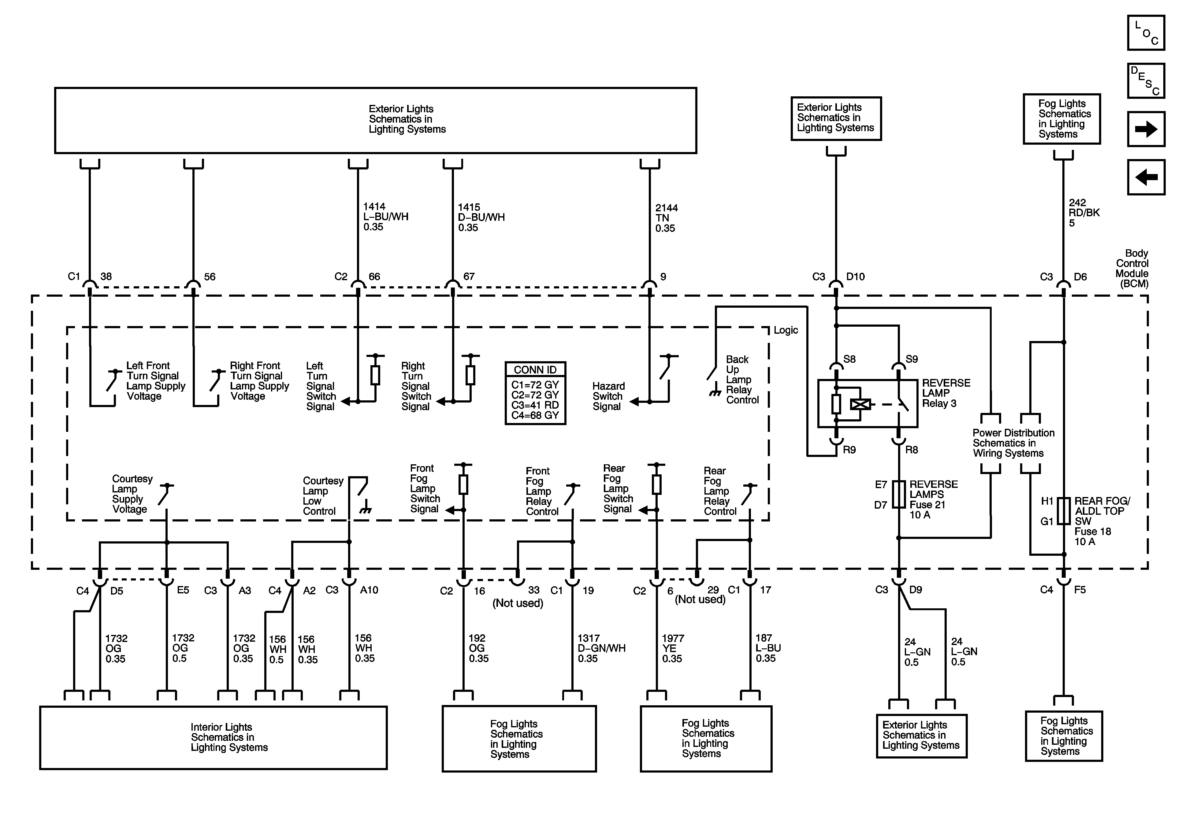
Figure
3:
Lighting References - 2 of 2
Master Electrical Component List
Body Control System Description and Operation
Subsystems References
Lighting References 1 of 2
Turn Signal and Hazard Lamps (Domestic)
Backup Lamps
Rear Fog Lamps (Europe)
Fuse Block-Underhood Fuses; BATT3 and STOP/B/U/LPS, BCM Fuses; BTSI SOL/COL LOCK, PWR FLDG MIR-EXT/RET, RADIO/ANT/VICS, REAR FOG/ALDL TOP SW, and REVERSE LAMPS
Lamp Controls, Courtesy, Underhood, I/P Compartment, Vanity Mirrors and Inside Rearview Mirror Lamps
Front Fog Lamps
Rear Fog Lamps (Europe)
Backup Lamps
Rear Fog Lamps (Europe)
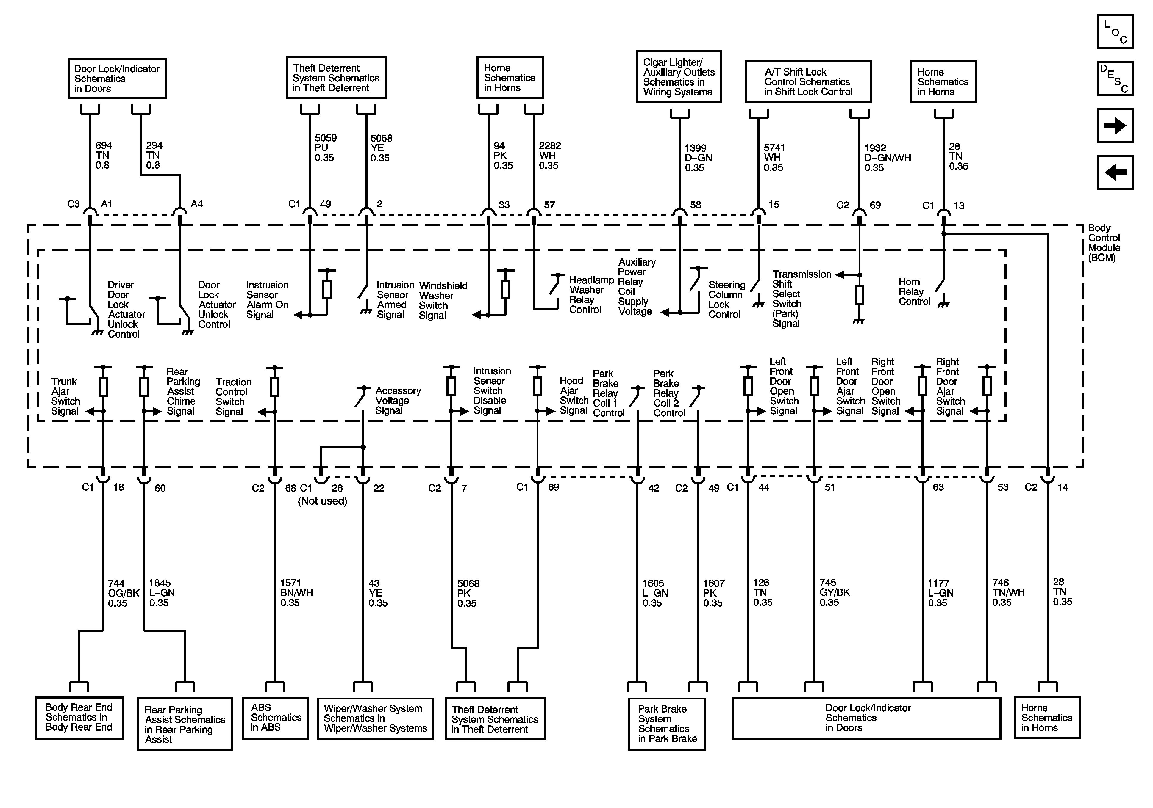
Figure
4:
Subsystems References
Master Electrical Component List
Body Control System Description and Operation
Auxiliary Power
Lighting References 2 of 2
Actuators and Handle Switches
Content Theft Deterrent
Wiper Switch, Washers andOutside Moisture Sensor
Cigar Lighter/ Auxiliary Outlet Schematics
A/T Shift Lock Control Schematics
Horns Schematic
Body Rear End Schematics
DLC, Ground, Power, and Non-Sensor Signals
Brake Pedal Signal, and Traction Control Switch
Power, Ground and Wiper Motor
Content Theft Deterrent
Park Brake System Schematics
Indicators, Messages, and Ajar/Open/Lock Switches
Horns Schematic
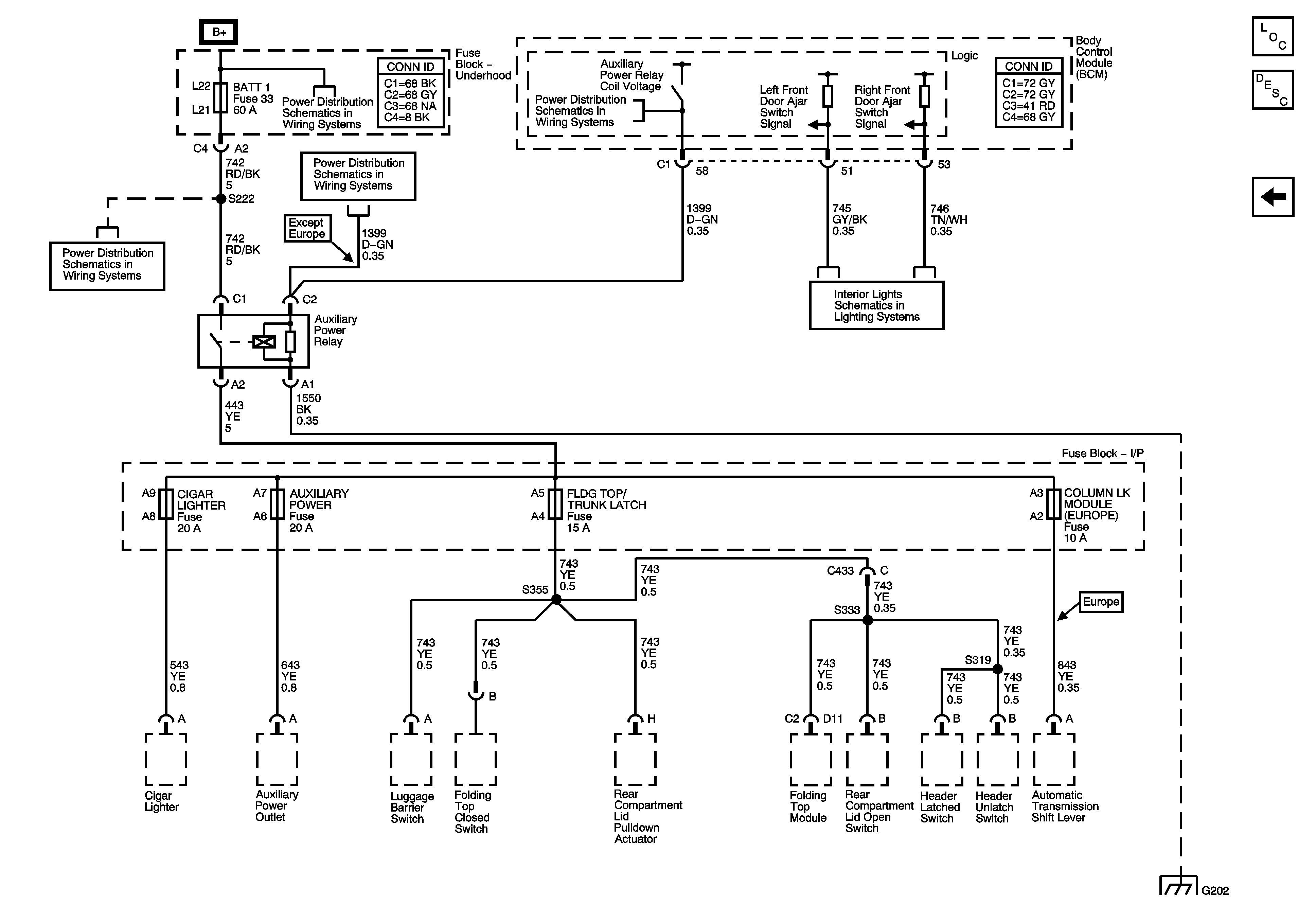
Figure
5:
Auxiliary Power
Master Electrical Component List
Body Control System Description and Operation
Subsystems References
Fuse Block-Underhood Fuse; BATT1, Fuse Block-I/P Fuses; HEATED SEAT LH, HEATED SEAT RH, POWER LUMBAR LH/RH, Fuse Block-I/P Circuit Breakers; DOOR CONTROLS, and POWER SEATS
Ignition Modes
Ignition Modes
Indicators, Messages, and Ajar/Open/Lock Switches