For 1990-2009 cars only
Removal Procedure
- Apply the parking brake.
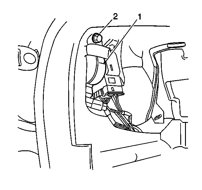
- Remove the right IP endcap. Refer to Instrument Panel Outer Trim Cover Replacement .
- Insert the ignition key and turn the ignition switch to RUN.
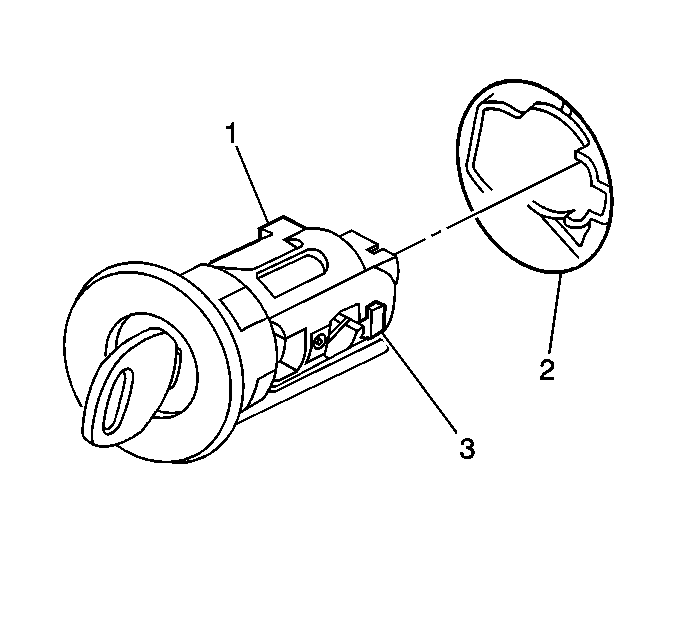
- Look through endcap opening in IP and locate the release button (1) on the side of the switch.
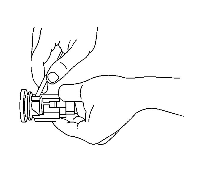
- Depress and hold the ignition lock cylinder retaining tab (located on the RH lower side of the ignition switch), using a flat bladed screwdriver or other suitable tool.
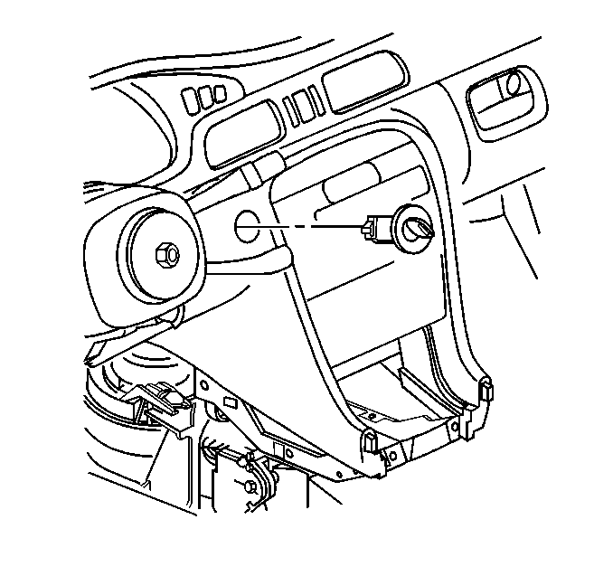
- Pull on the igntion cylinder to remove.
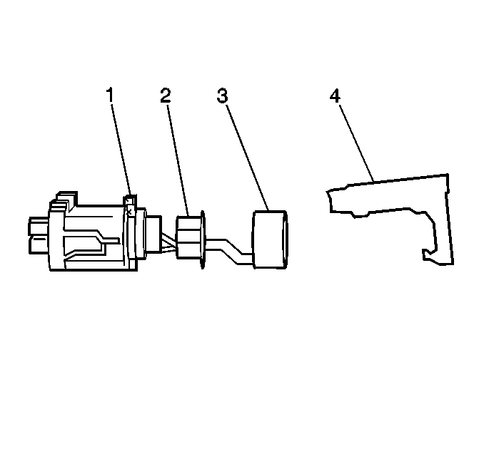
- Release the retainers from the ignition cylinder bezel.
- Slide the reader/exciter (4) and the cylinder cover (2) off from the ignition cylinder.
- Release the retainers from the light pipe (2) to cylinder.
Installation Procedure
- Install the ignition cylinder cover (2) and light pipe (3) onto ignition cylinder and engage the retainers.
- Slide the reader/exciter (4) onto ignition cylinder and align to slot on cylinder.
- Install the ignition cylinder bezel on the the cylinder and engage retainers.
- Insert the ignition lock cylinder (1) with the key installed into the ignition switch (2).
- Press the ignition lock cylinder into place.
- Check to be sure that the ignition lock cylinder is fully engaged.
- Turn the ignition to LOCK, then remove the key.
- Install the IP endcap. Refer to Instrument Panel Outer Trim Cover Replacement .
- Release the parking brake.
- Check the ignition switch for proper operation in all positions.

The lock cylinder retaining tab will produce an audible click.
| • | Use light force to pull lock cylinder and attempt to remove it. |
| • | The lock cylinder should not be removeable. |
