Tools Required
| • | J 41352 Modular Column Holding Fixture |
| • | J 42640 Steering Column Anti Rotation Pin |
- Remove the tilt lever assembly. Refer to Tilt Lever Replacement - On Vehicle .
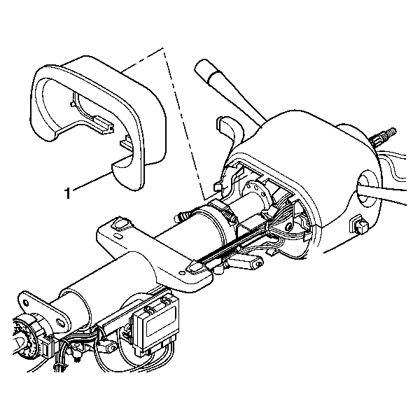
- Remove the steering column closeout trim cover (1).
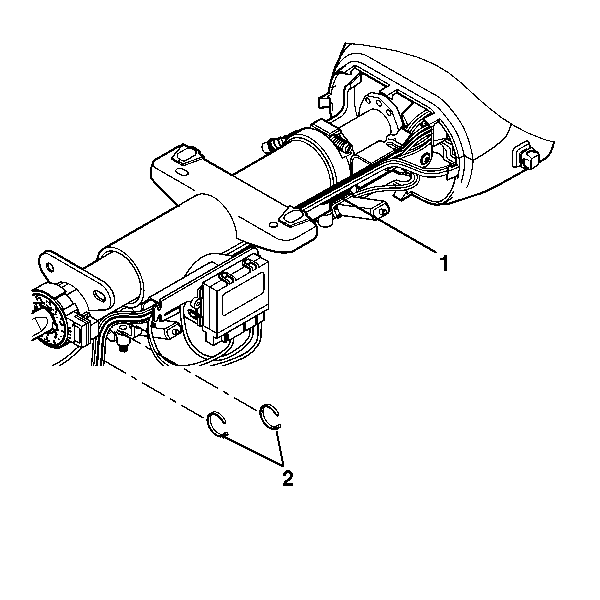
- Remove the 2 wire harness straps (2) from the wire harness assembly (1).
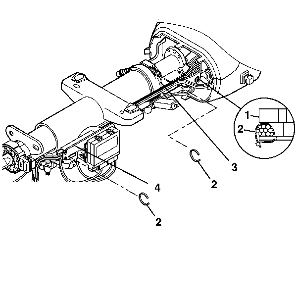
- Remove the wire harness strap (2) from the upper wire shield (3).
- Remove the wire harness strap (2) from the lower wire shield (4).
- Remove the wire harness strap (2) from the upper tilt head assembly (1).
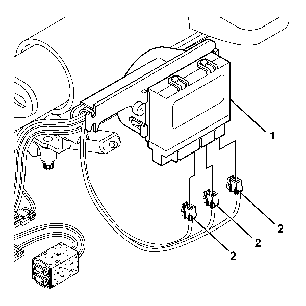
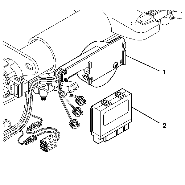
- Remove the 3 connectors (2) from the entertainment and comfort interface module assembly (1).
- Remove the entertainment and comfort interface module assembly (2) from the lower wire shield (1).
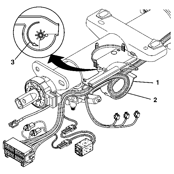
- Pop open the lower wire shield (1) and remove the wire harness assembly (2). Notice the direction (3) the wire harness assembly is routed.
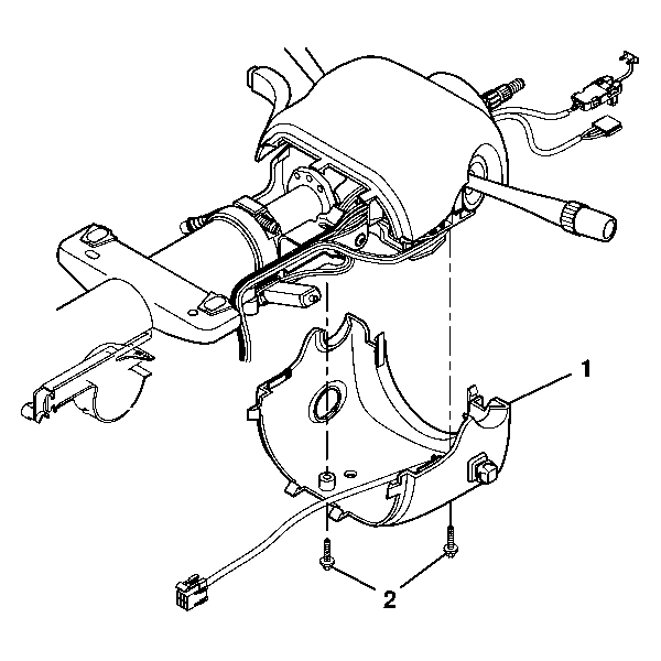
- Remove the 2 pan head tapping screws (2) from the lower trim cover (1).
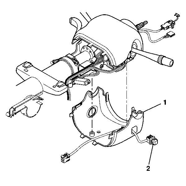
- Remove the lower trim cover (2).
- Remove the power tnt toggle switch assembly (2) from the lower trim cover (1).
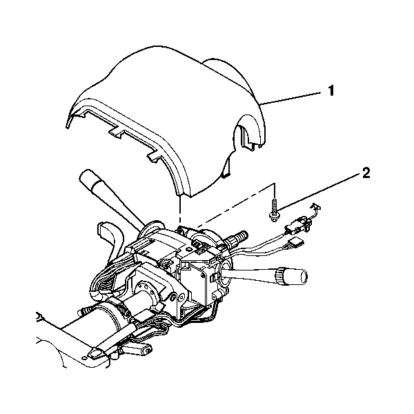
- Remove the TORX® head screw (2) from the upper trim cover (1).
- Remove the upper trim cover (1).
Important: Before any repair can take place, the column must be fully extended. After the soft stop, press the tilt lever button forward 8 more times, the column will override the soft stop and extend 3 mm more.
Tools Required
| • | J 41352 Modular Column Holding Fixture |
| • | J 42640 Steering Column Anti Rotation Pin |
- Install the upper trim cover (1) and secure by using the TORX® head screw (2).
- Install the power tnt toggle switch assembly (2) into the lower trim cover (1).
- Install the lower trim cover (1).
- Install the 2 pan head tapping screws (2) to the lower trim cover (1).
- Route the wire harness assembly (2). Notice the direction (3) the wire harness assembly (2) goes into the lower wire shield (1).
- Install the entertainment and comfort interface module assembly (2) into the lower wire shield (1).
- Install the 3 connectors (2) into the entertainment and comfort interface module assembly (1).
- Install the wire harness strap (2) to the upper wire shield (3).
- Install the wire harness strap (2) to the lower wire shield (4).
- Install one wire harness strap (2) to the upper tilt head assembly (1).
- Install the 2 wire harness straps (2) to the wire harness assembly (1).
- Install the steering column closeout trim cover (1).
- Install the tilt lever assembly. Refer to Tilt Lever Replacement - On Vehicle .

Notice: Use the correct fastener in the correct location. Replacement fasteners must be the correct part number for that application. Fasteners requiring replacement or fasteners requiring the use of thread locking compound or sealant are identified in the service procedure. Do not use paints, lubricants, or corrosion inhibitors on fasteners or fastener joint surfaces unless specified. These coatings affect fastener torque and joint clamping force and may damage the fastener. Use the correct tightening sequence and specifications when installing fasteners in order to avoid damage to parts and systems.
Tighten
Tighten the screws to 1.5 N·m (13 lb in).


Tighten
Tighten the screws to 3.5 N·m (31 lb in).


