High Intensity Discharge Headlamp Ballast Replacement TT6, TT7, TT8
Removal Procedure
Caution: The high intensity discharge system produces high voltage and current.
To reduce the risk of severe shocks and burns:
• Never open the high intensity discharge system ballast or the
arc tube assembly starter. • Never probe between the high intensity discharge system ballast
output connector and the arc tube assembly.
- Remove the low beam headlamp relay in order to disable the HID (High Intensity Discharge) headlamp system. Refer to Headlamp Relay Replacement .
- Remove the headlamp. Refer to Headlamp Replacement .
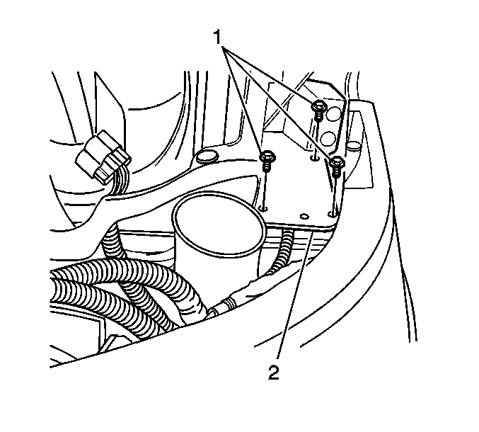
- Remove the 3 fasteners (1) that secure the HID ballast to the underside of the headlamp mounting bracket (2).
- Disconnect the HID ballast electrical connector.
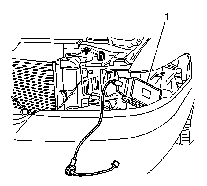
- Remove the HID ballast (1) from the opening between the headlamp mounting bracket and the front bumper cover.
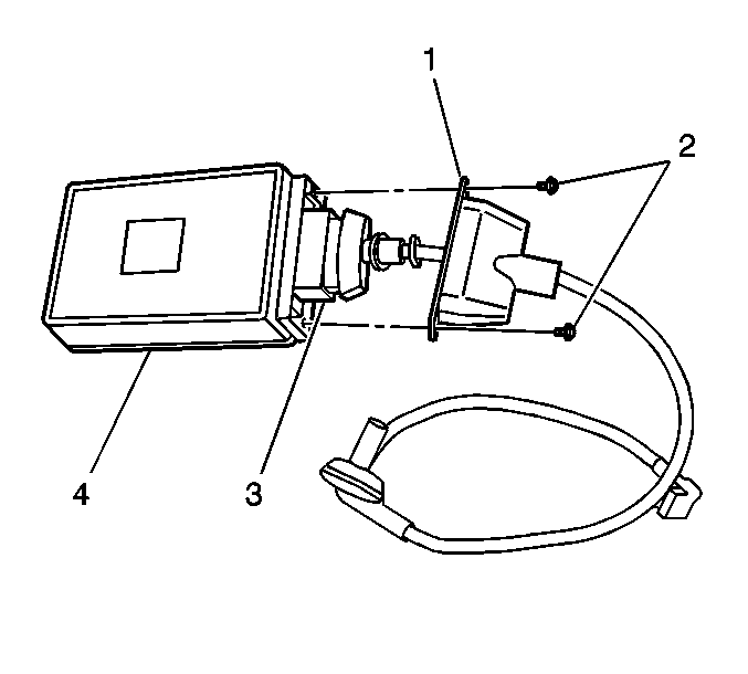
- Remove the ballast cable connection cover (1) from the ballast (4), by removing the 2 fasteners that secure the cover.
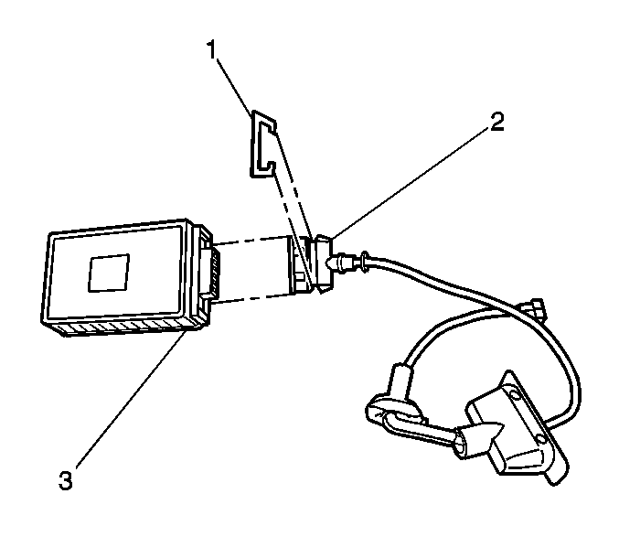
- Remove the connector position assurance (CPA) (1) from the HID ballast electrical connector (2).
- Remove the electrical connector and cable assembly (2) from the HID ballast (3).

The HID ballast feed electrical connector is located towards the rear of the ballast, opposite the arc tube and starter cable connection.

Important: The HID ballast will need to be rotated approximately 90° in order to remove the ballast from the opening between the headlamp mounting bracket and the front bumper cover.


Installation Procedure
- Install the electrical connector and cable assembly (2) to the ballast (3).
- Install the (CPA) (1) to the ballast electrical connector (2).
- Install the ballast cable connection cover (1) to the ballast (4).
- Install the ballast cable connection cover fasteners (2).
- Install the HID ballast (1) to the vehicle.
- Connect the HID ballast (1) feed electrical connection.
- Install the 3 HID ballast fasteners (1) in order to secure the HID ballast to the headlamp mounting bracket (2).
- Install the headlamp. Refer to Headlamp Replacement .
- Install the low beam headlamp relay. Refer to Headlamp Relay Replacement .


Notice: Use the correct fastener in the correct location. Replacement fasteners must be the correct part number for that application. Fasteners requiring replacement or fasteners requiring the use of thread locking compound or sealant are identified in the service procedure. Do not use paints, lubricants, or corrosion inhibitors on fasteners or fastener joint surfaces unless specified. These coatings affect fastener torque and joint clamping force and may damage the fastener. Use the correct tightening sequence and specifications when installing fasteners in order to avoid damage to parts and systems.
Tighten
Fasteners for the ballast cover (1) should be fully driven, seated
and not stripped.


Tighten
Tighten the ballast fasteners to 5.5 N·m (49 lb in).
Important: Ensure the grommet attached to the arc tube and starter is properly installed and sealed to the headlamp assembly, in order to avoid water intrusion in the headlamp assembly.
Ensure the arc tube and starter cover is properly installed and sealed to the headlamp assembly in order to avoid water intrusion in the headlamp assembly.