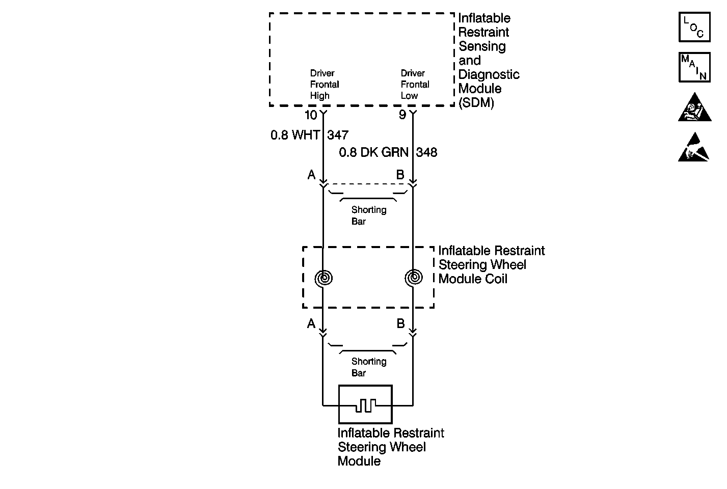
Circuit Description
When you first turn the ignition switch to the ON position, the inflatable restraint sensing and diagnostic module (SDM) performs tests to diagnose critical malfunctions within itself. Next the SDM measures Ignition 1 voltage to make sure it is within its respective normal voltage range. Then the SDM proceeds with the Deployment Loop Continuity test. During the Deployment Loop Continuity test, the SDM measures the voltage difference between Driver Frontal High and Driver Frontal Low.
Conditions for Setting the DTC
| • | The voltage difference between Driver Frontal High terminal 10 and Driver Frontal Low terminal 9 is more than or equal to 426 millivolts. |
| • | The malfunction must be present for at least 500 milliseconds during one of the following tests: |
| - | Deployment Loop Continuity |
| - | If the malfunction is detected in this test, the Resistance Measurement test will not be performed. |
| - | Continuous Monitoring |
Action Taken When the DTC Sets
| • | The SDM sets a Diagnostic Trouble Code (DTC). |
| • | The SDM command the instrument cluster (IPC) to turn ON the AIR BAG warning lamp. |
Conditions for Clearing the MIL/DTC
| • | Current DTC |
| The voltage difference between Driver Frontal High terminal 10 and Driver Frontal Low terminal 9 is less than 426 millivolts for 500 milliseconds. |
| • | History DTC |
| - | You issue a scan tool Clear DTCs command. |
| - | Once 250 malfunction free ignition cycles have occurred. |
Diagnostic Aids
The following can cause an intermittent condition:
| • | A poor connection at the inflatable restraint steering wheel module column connector terminals A and B. |
| • | A poor connection at the upper inflatable restraint steering wheel coil connector terminal A and B. |
| • | A poor connection at the SDM terminals 10 and 9. |
| • | An open in CKT 347. |
| • | An open in CKT 348. |
An intermittent open in the inflatable restraint steering wheel module coil could also set this DTC. In order to test for a bad inflatable restraint steering wheel module coil, clear the DTCs, then turn the steering wheel back and forth with the ignition switch in the ON position. If the AIR BAG warning lamp comes ON and DTC B1126 has set again, it is likely the inflatable restraint steering wheel module coil is malfunctioning.
The diagnostic table directs the technician to note the scan tool value of Driver Frontal VDIF. Comparing the value of Driver Frontal VDIF can be helpful in determining if an intermittent condition exists.
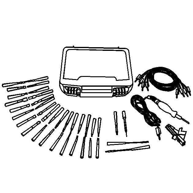
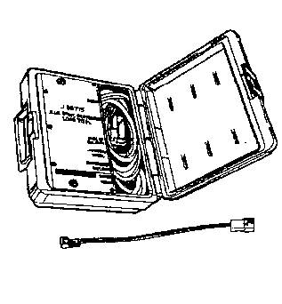
When measurements are requested in this table, use J 39200 Digital Multimeter with the correct terminal adapter from J 35616 Connector Test Adapter Kit. When a check for proper connection is requested, refer to General Electrical Diagnosis in Wiring Systems. When a wire, connector or terminal repair is requested, use J-38125 Terminal Repair Kit and refer to Wiring Repair .
Test Description
The numbers below refer to the step numbers on the diagnostic table:
-
This test determines the deployment loop voltage difference measured by the inflatable restraint sensing and diagnostic module (SDM).
-
This test checks for proper contact or corrosion of the yellow 2-way connector.
-
This test isolates the malfunction to one side of the inflatable restraint steering wheel module coil yellow 2-way connector.
-
This test determines whether the malfunction is due to the inflatable restraint steering wheel module or the module coil.
-
This test checks for proper contact or corrosion of the SDM connector.
-
This test determines whether the malfunction is in CKT 347.
-
This test determines whether the malfunction is in CKT 348.
Step | Action | Value(s) | Yes | No |
|---|---|---|---|---|
1 | Was the SIR Diagnostic System Check performed? | -- | Go to Step 2 | |
Has the Driver Frontal VDIF been read and recorded on the repair order? | -- | Go to Step 3 | -- | |
Are the terminals damaged or corroded? | -- | Go to Step 4 | Go to Step 6 | |
4 | Replace the inflatable restraint steering wheel module yellow 2-way harness connector. Refer to Wiring Repair . Did you complete the repair? | -- | Go to Step 5 | -- |
5 | Check for proper connection at terminals A and B on the coil side of the connector. Are the terminals damaged or corroded? | -- | Go to Step 7 | Go to Step 23 |
6 | Check for proper connection at terminals A and B on the coil side of the connector. Are the terminals damaged or corroded? | -- | Go to Step 7 | Go to Step 8 |
7 | Replace the inflatable restraint steering wheel module coil. Refer to Inflatable Restraint Steering Wheel Module Coil Replacement . Did you complete the replacement? | -- | Go to Step 23 | -- |
8 |
Is the Driver Frontal VDIF greater than the specified value? | 426 mV | Go to Step 10 | Go to Step 9 |
9 |
Did you complete the repair? | -- | Go to Step 23 | -- |
Is the Driver Frontal VDIF greater than the specified value? | 426 mV | Go to Step 14 | Go to Step 11 | |
Is the Driver Frontal VDIF greater than the specified value? | 426 mV | Go to Step 13 | Go to Step 12 | |
12 |
Did you complete the replacement? | -- | Go to Step 23 | -- |
13 |
Did you complete the replacement? | -- | Go to Step 23 | -- |
Is the connector damaged or corroded? | -- | Go to Step 15 | Go to Step 17 | |
15 | Replace the SDM harness connector. Refer to Connector Repairs in Wiring Systems. Did you complete the repair? | -- | Go to Step 16 | -- |
16 | Check for proper connection at terminals 10 and 9 of the SDM. Are the terminals damaged or corroded? | -- | Go to Step 18 | Go to Step 23 |
17 | Check for proper connection at terminals 10 and 9 of the SDM. Are the terminals damaged or corroded? | -- | Go to Step 18 | Go to Step 19 |
18 | Replace the inflatable restraint sensing and diagnostic module (SDM). Refer to Inflatable Restraint Sensing and Diagnostic Module Replacement . Did you complete the replacement? | -- | Go to Step 23 | -- |
Using J 39200 DMM, measure the resistance from the SDM harness connector terminal 10 to the inflatable restraint steering wheel module yellow 2-way harness connector terminal A. Is the resistance reading within the specified values? | 0.0-0.5 ohms | Go to Step 21 | Go to Step 20 | |
20 | Repair the high resistance condition in CKT 347. Refer to Wiring Repair . Did you complete the repair? | -- | Go to Step 23 | -- |
Using J 39200 DMM, measure the resistance from the SDM harness connector terminal 9 to the inflatable restraint steering wheel module yellow 2-way harness connector terminal B. Is the resistance reading within the specified values? | 0.0-0.5 ohms | Go to Step 22 | ||
22 | Repair the high resistance condition in CKT 348. Refer to Wiring Repair . Did you complete the repair? | -- | Go to Step 23 | -- |
23 | Reconnect all the SIR system components, make sure all the components are properly mounted. Have all the SIR components been reconnected and properly mounted? | -- | Go to Step 24 | -- |
24 | Clear all the SIR DTCs. Have all the SIR DTCs been cleared? | -- | -- |
