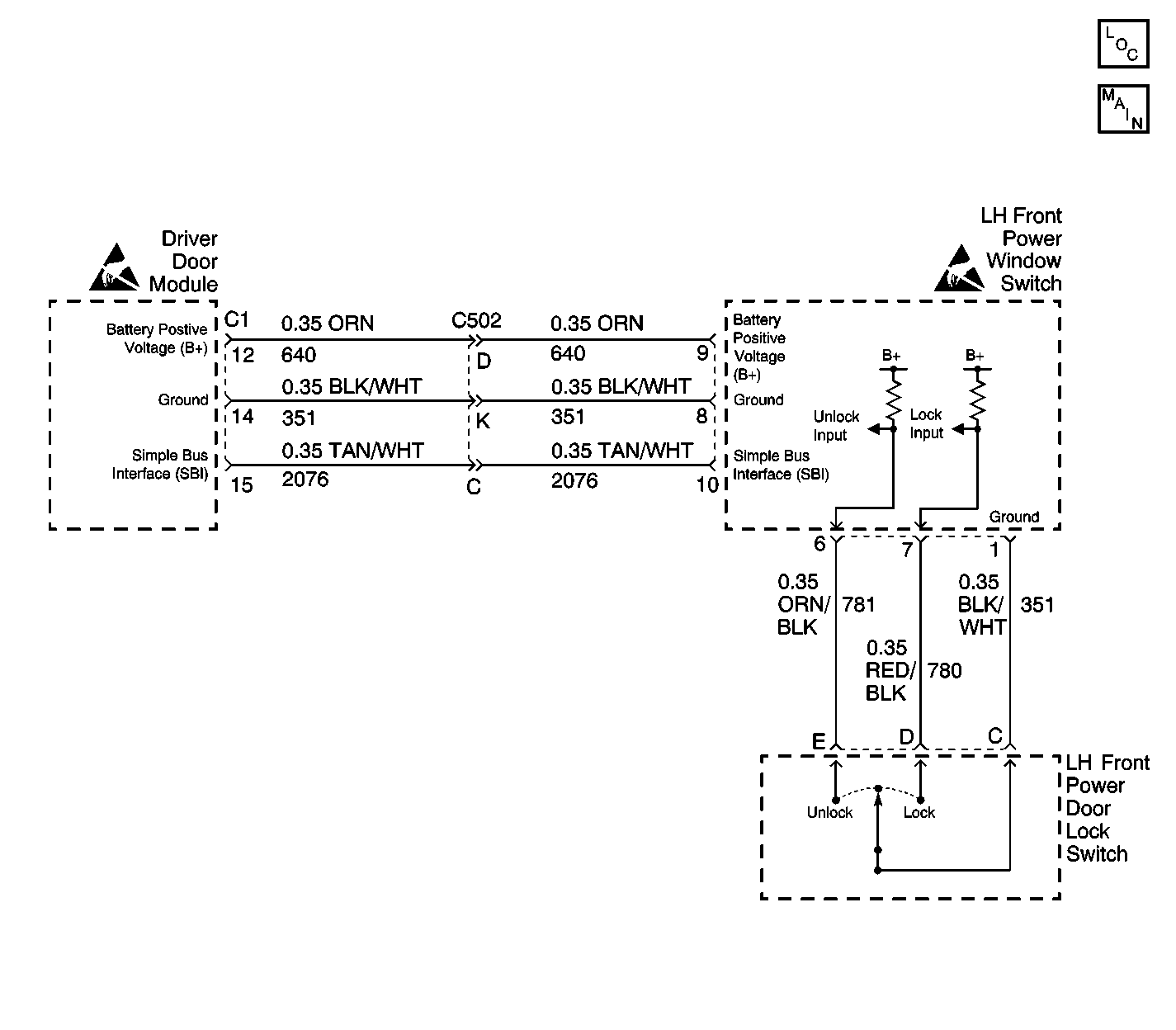
Circuit Description
The LH Front Power Door Lock Switch provides the LH Front seat occupant with the ability to initiate a lock all doors signal.
Whenever the Power Door Lock Switch is moved to the LOCK position, a ground is placed on the LH Front Power Window Switch Connector, terminal 7 input, through CKT 780 (RED/BLK).
The Power Door Lock Switch ground is provided from the LH Front Door Module via CKT 351 (BLK/WHT). If CKT 351 (BLK/WHT) is open or has a high resistance the LH Front power window will also exhibit problems. Splice S500 is the common ground point for both the Power Door Lock Switch and the Power Window Switch.
Power Window Switch power is furnished through CKT 640 (ORN). If CKT 640 (ORN) is open or shorted to ground, the LH Front power window will also exhibit problems.
When this Power Door Lock Switch is placed in the LOCK position, the lock signal is sensed by the Power Window Switch, which then formats a digital message relating this switch activity. This digital message is then sent to the driver door module over the Simple Bus Interface (SBI). The driver door module relays this message to the Rear Interface Module (RIM), requesting a command to lock all doors. The RIM is the door lock master. The RIM will check to see is the key is in the ignition and a door is open prior to sending a lock all doors command. Any problem with the SBI or driver door module will affect all door lock and window functions. Problems with the RIM will show up in a number of other subsystems including:
| • | Rear Seat Heat |
| • | Theft |
| • | Courtesy Lamps |
| • | Park Brake |
| • | Rear Fog Lamp |
| • | Rear Defog |
| • | Release Systems |
| • | Rear Blower |
| • | Retained Accessory Power |
| • | Cigar Lighter |
Conditions for Setting the DTC
If the LOCK signal to the LH Front Power Window Switch remains grounded for a period of 30 seconds, this DTC will become active (current). The LOCK signal from CKT 780 (RED/BLK) is examined by the LH Front Power Window Switch no less than once every 300 milliseconds.
The diagnostic for this DTC will not run if either DTC B1982 (Battery Voltage High) or B1983 (Battery Voltage Low) is set (current).
Action Taken When the DTC Sets
This DTC is dynamic, and as such, is set only while the fault is active. This switch actuation will be ignored by the door module until a switch change of state is detected.
Conditions for Clearing the MIL/DTC
| • | This DTC will be set from current to history when the LOCK input cycles off or the power mode changes from OFF to RUN. |
| • | A history DTC will clear after 50 consecutive ignition cycles if the condition for the malfunction is no longer present. |
| • | Use the On-Board clearing DTC feature. |
| • | Use a scan tool. |
Diagnostic Aids
| • | A history DTC is evidence of a intermittent condition, clear the DTC and cycle the ignition switch from OFF to RUN. Then perform the Diagnostic System Check. |
| • | If DTC B2220 is current, cycle the ignition switch from OFF to RUN. If this DTC is still current, perform the following diagnostic. |
Test Description
Numbers below refer to the Diagnostic Table Step Number(s).
-
Perform the system check prior to diagnosis.
-
Checking the LH Front Power Door Switch for an internal short.
-
This repair procedure requires power window switch replacement.
-
Checking the LH Front Power Door Lock Switch operation.
-
This repair procedure requires the repair CKT 780 for a short to ground.
-
This repair procedure requires LH Front Power Window Switch replacement.
-
Clear all DTCs following repair procedure completion.
Step | Action | Value(s) | Yes | No |
|---|---|---|---|---|
Was the Power Door Systems Diagnostic System Check performed? | -- | Go to Step 2 | ||
Is the resistance within the specified range? | 0-5 ohms | Go to Step 3 | Go to Step 4 | |
Replace the LH Front Power Door Lock Switch. Refer to Door Lock Switch Replacement . Is the repair complete? | -- | Go to Step 7 | -- | |
Is the voltage within specified range? | 10-15 V | Go to Step 6 | Go to Step 5 | |
Repair CKT 780 for a short to ground. Refer to Wiring Repairs in Wiring Systems. Is the repair complete? | -- | Go to Step 7 | -- | |
Replace the LH Front Power Window Switch. Refer to Front Door Switch Replacement . Is the replacement complete? | -- | Go to Step 7 | -- | |
Are all DTCs cleared? | -- | -- |
