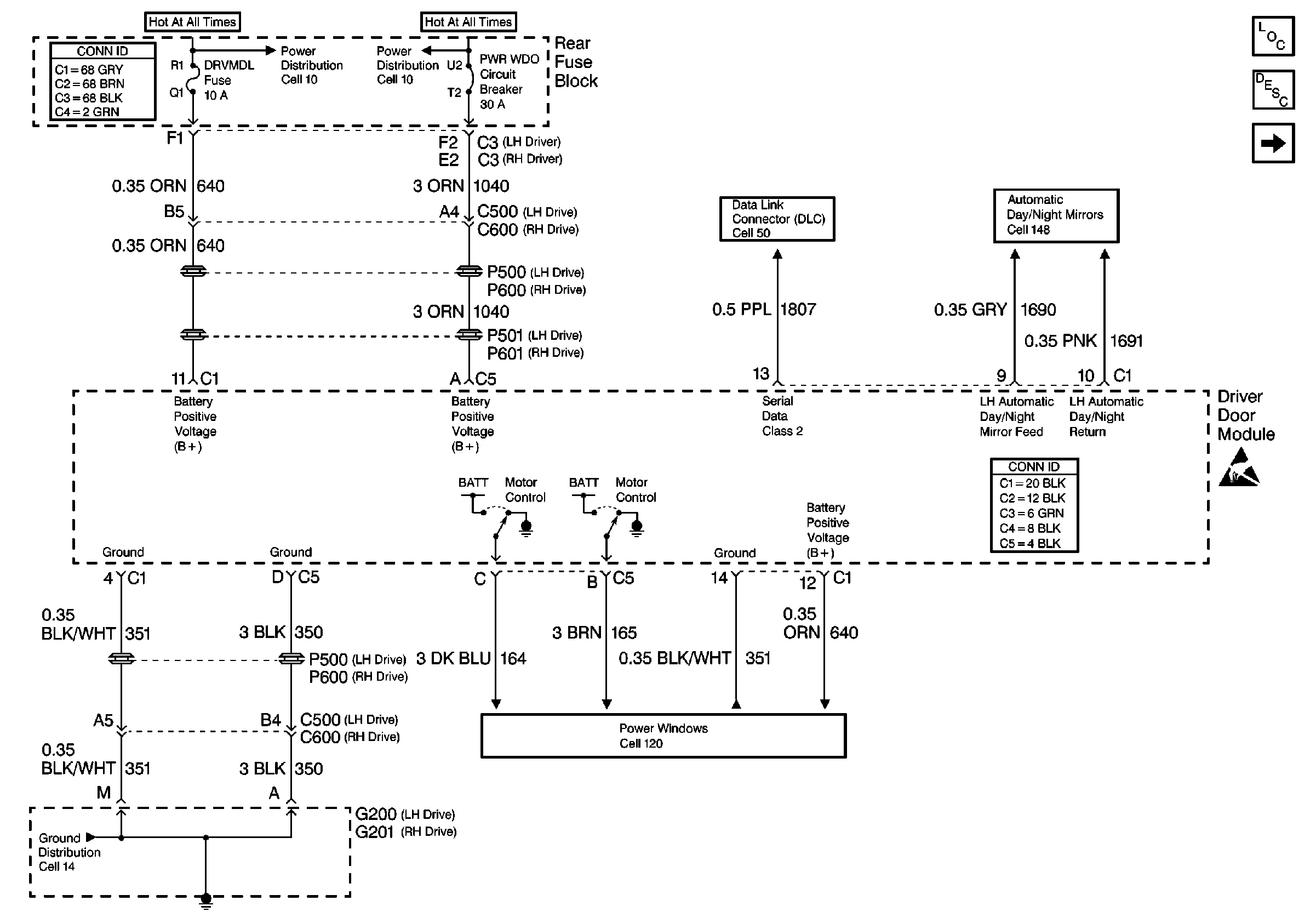
Refer to Door Control Module Schematics
Cell 55: Driver Door Module Inputs and Outputs

Circuit Description
The driver door module performs internal tests on the EEPROM each time that the driver door module performs a write function to a memory address in the EEPROM. The driver door module reads back the data that has been written and compares it to the data. If the data does not match after 3 consecutive write and verify attempts, the driver door module will indicate a write malfunction is current.
Conditions for Setting the DTC
| • | The data read back after a write does not match the data being written 3 consecutive times. |
| • | The driver door module detects an internal write malfunction. |
| • | The condition must occur when data is being written. |
Action Taken When the DTC Sets
| • | Stores a DTC B1656 in the driver door module memory. |
| • | No driver warning message will be displayed for this DTC. |
| • | The driver door module will store the value being written in another memory address in the EEPROM. |
Conditions for Clearing the DTC
| • | This DTC requires a successful write in order to change from current to history. |
| • | The driver door module no longer detects an internal write malfunction. |
| • | A history DTC will clear after 50 consecutive ignition cycles if the condition for the malfunction is no longer present. |
| • | Use the On-Boards clearing DTCs feature. |
| • | Use a scan tool. |
Diagnostic Aids
Since the EEPROM cannot be removed from the driver door module and DTC B1656 is an internal driver door module malfunction, the driver door module may be replaced.
Test Description
The numbers below refer to the step numbers on the diagnostic table:
-
Perform the Door Control System Diagnostic System Check before continuing with the diagnosis of this DTC.
-
Clear all DTCs and cycle ignition to check that the DTC did not falsely set.
-
Clear all DTCs after the repair procedure is complete.
Step | Action | Value(s) | Yes | No |
|---|---|---|---|---|
Was the Power Door System Diagnostic System Check performed? | -- | Go to Step 2 | ||
Is the DTC still present? | -- | Go to Step 3 | ||
3 | Replace the driver door module. Refer to Door Control Module Replacement . Is the repair complete? | -- | Go to Step 4 | -- |
Are all DTCs cleared? | -- | -- |
