GM Service Manual Online
For 1990-2009 cars only
Figure 1:

Cell 51: DIM Power and Ground


Object Number: 383449  Size: FS
Cell 10: IGN, SW, HTDST LR, HTDST RR, and HTDST RF Fuses
Body Control Module Components
Body Control System Circuit Description
Cell 51: DIM Ignition Inputs
Cell 50: Class 2 Serial Data Line (LH Drive)
Cell 14: G201 (1 of 3)
Figure 2:

Cell 51: DIM Ignition Inputs


Object Number: 383483  Size: FS
Cell 10: Ignition Switch
Body Control Module Components
Body Control System Circuit Description
Cell 51: DIM Inputs and Outputs (1 of 2)
Cell 51: DIM Power and Ground
Cell 10: Ignition Switch
Cell 10: IGN 3 Relay and HVAC, ABS Fuses
Cell 10: START Circuit Breaker and ACC, WSW Fuses
Cell 10: Ignition Switch
Figure 3:

Cell 51: DIM Inputs and Outputs (1 of 2)


Object Number: 383456  Size: FS
Body Control Module Components
Body Control System Circuit Description
Cell 51: DIM Inputs and Outputs (2 of 2)
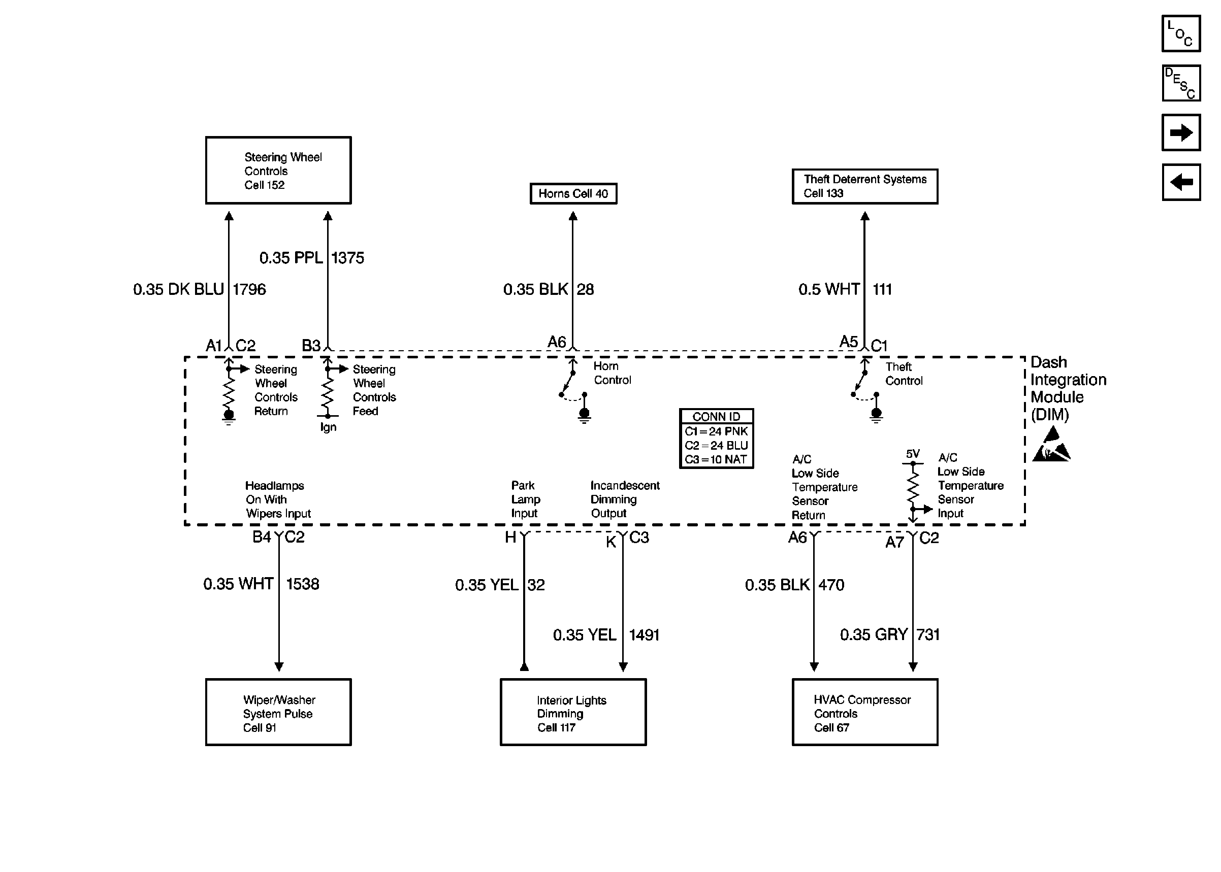
Cell 51: DIM Ignition Inputs
Fog Lights Schematics Front
Interior Lights Schematics
Headlights Schematics Domestic
Cell 14: G104
Figure 4:

Cell 51: DIM Inputs and Outputs (2 of 2)


Object Number: 154532  Size: FS
Steering Wheel Controls Schematics
Horn Schematics
Theft Deterrent System Schematics
Wiper/Washer System (Pulse) Schematics
Interior Lights Dimming Schematics
Cell 67
Body Control Module Components
Body Control System Circuit Description
Cell 51: IPM Power and Ground
Cell 51: DIM Inputs and Outputs (1 of 2)
Handling ESD Sensitive Parts Notice
Figure 5:

Cell 51: IPM Power and Ground


Object Number: 383462  Size: FS
Handling ESD Sensitive Parts Notice
Body Control Module Components
Body Control System Circuit Description
Cell 51: IPM Inputs and Outputs (1 of 2)
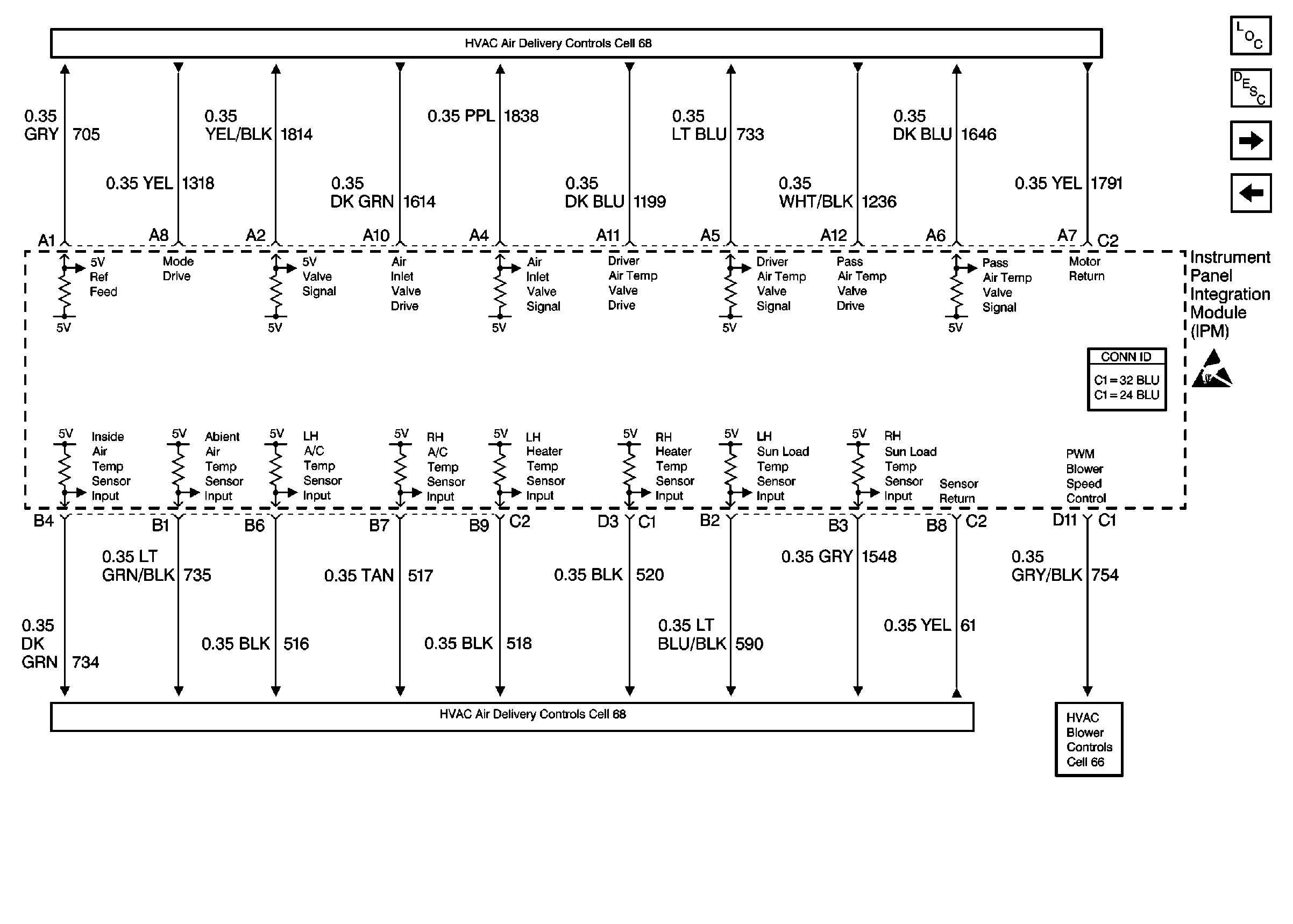
Cell 51: DIM Inputs and Outputs (2 of 2)
Cell 14: G201 (1 of 3)
Data Link Connector Schematics
Cell 10: PCM BATT, EXPORT BRK, IP, ABS SOL, and ABS MOT Fuses
Cell 10: IGN 3 RR Fuses
Figure 6:

Cell 51: IPM Inputs and Outputs (1 of 2)


Object Number: 154547  Size: FS
Cell 68: Electric Actuators
Cell 66: Front
Handling ESD Sensitive Parts Notice
Body Control Module Components
Body Control System Circuit Description
Cell 51: IPM Inputs and Outputs (2 of 2)
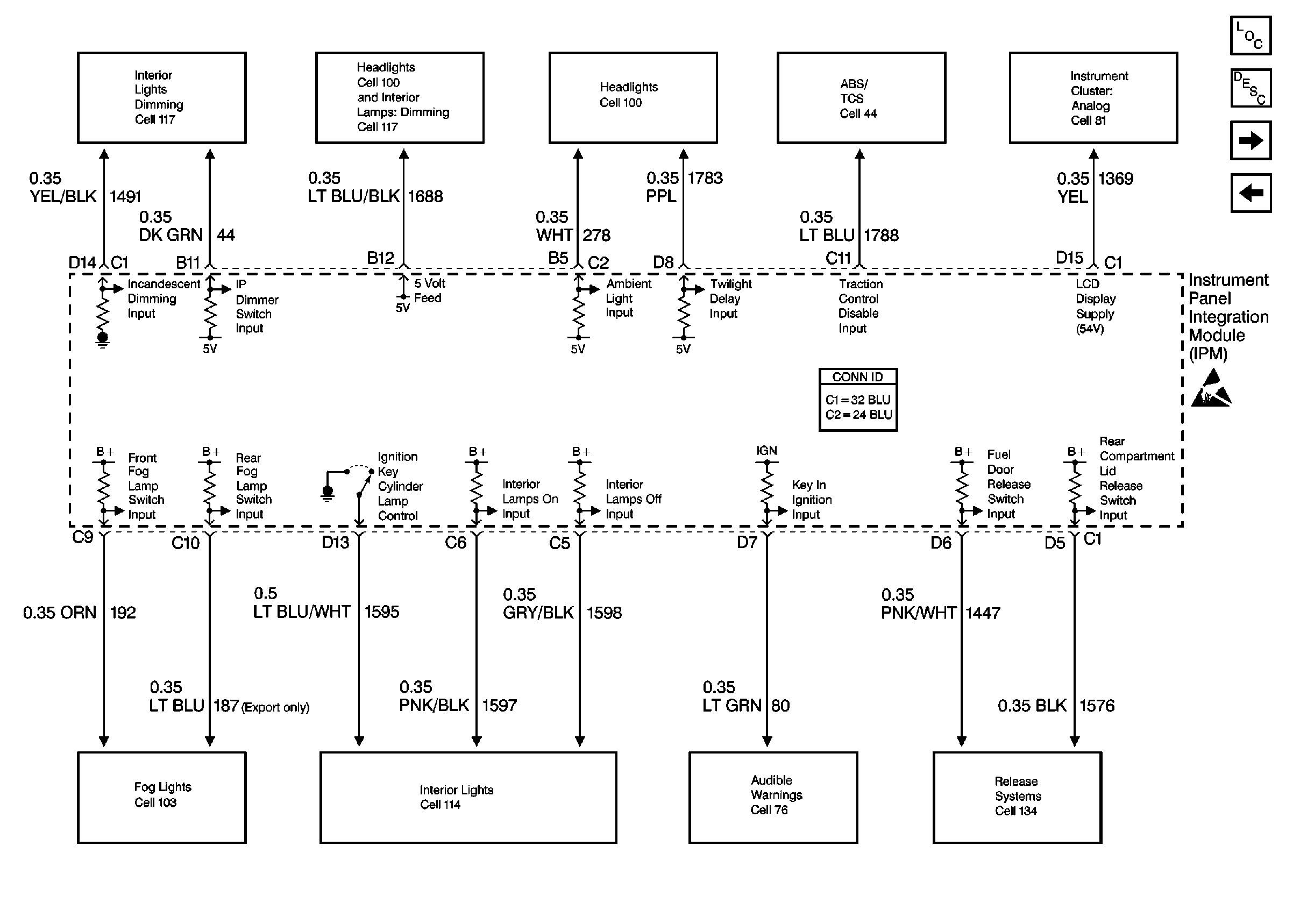
Cell 51: IPM Power and Ground
Figure 7:

Cell 51: IPM Inputs and Outputs (2 of 2)


Object Number: 154554  Size: FS
Interior Lights Dimming Schematics
Headlights Schematics Domestic
Antilock Brake System Schematics
PWR WDO and PWR SEAT Circuit Breakers (Rear Fuse Block)
Body Control Module Components
Body Control System Circuit Description
Cell 51: RIM Power and Ground
Cell 51: IPM Inputs and Outputs (1 of 2)
Handling ESD Sensitive Parts Notice
Fog Lights Schematics Front
Interior Lights Schematics
Audible Warnings Schematics
Release Systems Schematics
Figure 8:

Cell 51: RIM Power and Ground


Object Number: 383477  Size: FS
Cell 10: IGN, SW, HTDST LR, HTDST RR, and HTDST RF Fuses
Cell 10: IGN 1 Relay and SIR, VENT SOL, IGN1 Fuses
Cell 50: Class 2 Serial Data Line (RH Drive)
Cell 14: G401 (1 of 3)
Cell 10: IGN 1 Relay and SIR, VENT SOL, IGN1 Fuses
Cell 10: IGN, SW, HTDST LR, HTDST RR, and HTDST RF Fuses
Handling ESD Sensitive Parts Notice
Body Control Module Components
Body Control System Circuit Description
Cell 51: RIM Inputs and Outputs (1 of 2)
Cell 51: IPM Inputs and Outputs (1 of 2)
Figure 9:

Cell 51: RIM Inputs and Outputs (1 of 2)


Object Number: 383468  Size: FS
Interior Lights Schematics
Cigar Lighter/Power Outlet Schematics
Interior Lights Schematics
Cell 148: Inside Mirror
Fog Lights Schematics Front
Body Control Module Components
Body Control System Circuit Description
Cell 51: RIM Inputs and Outputs (2 of 2)
Cell 51: RIM Power and Ground
Retained Accessory Power (RAP) Schematics
Theft Deterrent System Schematics
Instrument Cluster: Analog Schematics
Release Systems Schematics
Handling ESD Sensitive Parts Notice
Figure 10:

Cell 51: RIM Inputs and Outputs (2 of 2)


Object Number: 383473  Size: FS
Body Control Module Components
Body Control System Circuit Description
Cell 51: RIM Inputs and Outputs (1 of 2)
Cell 61
Cell 66: Rear
Cell 143: LH Front Heated Seat
Park Brake System Schematics
Handling ESD Sensitive Parts Notice