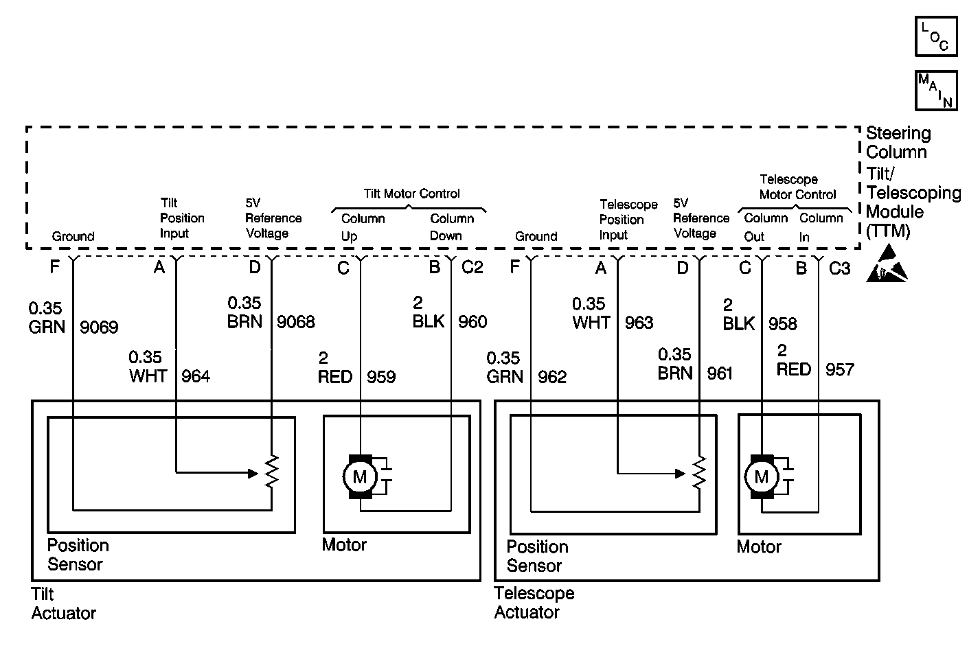
Circuit Description
The steering column tilt/telescoping module (TTM) provides 5 volt reference voltage to the tilt position sensor across TTM connector C2 terminals D and F and to the telescope position sensor across TTM connector C3 terminals D and F. The TTM monitors this voltage to determine if it is within a valid operating range.
Conditions for Setting the DTC
The 5 volt feed monitored within the module falls out of the limits 4.6 volts to 5.2 volts.
Action Taken When the DTC Sets
| • | Stores a DTC B1396 in TTM memory. |
| • | The TTM does not respond to any manual or memory inputs when the voltage is out of range. |
| • | The TTM switch failure and position sensor failure DTCs do not set while DTC B1396 is current. |
| • | No driver warning message are displayed for this DTC. |
Conditions for Clearing the DTC
| • | The 5 volt feed monitored within the module is within the limits 4.6 volts to 5.2 volts for approximately 1.2 seconds. |
| • | Use the On-Boards clearing DTCs feature. |
| • | Use a scan tool. |
Diagnostic Aids
Refer to the diagnostic chart.
Test Description
The numbers below refer to the step numbers on the diagnostic table:
-
Perform the Tilt/Telescoping Steering Column Diagnostic System Check before continuing with the diagnosis of this DTC.
-
Clear all DTCs after the repair procedure is complete.
Step | Action | Value(s) | Yes | No |
|---|---|---|---|---|
Was the Tilt/Telescoping Steering Column Diagnostic System Check performed? | -- | Go to Tilt/Telescoping Steering Column Diagnostic System Check | ||
2 |
Does DTC B1396 set again? | -- | ||
3 | Replace the tilt actuator. Refer to Tilt Actuator Assembly Replacement - On Vehicle . Is the replacement complete? | -- | -- | |
4 |
Does DTC B1396 set again? | -- | ||
5 | Replace the telescope actuator. Refer to Telescope Actuator Assembly Replacement - On Vehicle . Is the replacement complete? | -- | -- | |
6 |
Is the repair complete? | -- | -- | |
Is the Diagnostic System Check complete? | -- | System OK | -- |
