Tools Required
| • | J 28467-B Universal Engine Support Fixture |
| • | J 39580 Engine Support Stand |
| • | J 41160 Transmission Jack Adapter |
Removal Procedure
- Disconnect the battery negative cable from the battery. Refer to Battery Negative Cable Disconnection and Connection in Engine Electrical.
- Drain the cooling system. Refer to Cooling System Draining and Filling in Engine Cooling.
- Remove the upper filler panel. Refer to Filler Panel Replacement - Upper in Body Front End.
- Remove the air cleaner upper plenum and intake tube. Refer to Air Cleaner Assembly Replacement in Engine Controls.
- Remove the surge tank inlet pipe. Refer to Surge Tank Pipe Replacement - Inlet in Engine Cooling.
- Remove the surge tank outlet pipe. Refer to Surge Tank Pipe Replacement - Outlet in Engine Cooling.
- Remove the oil cooler lines at the cooler and the oil sending line at the transmission. Install plugs in the inlet and the return hose to prevent fluid leakage or contamination.
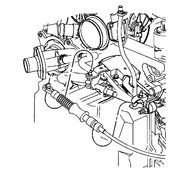
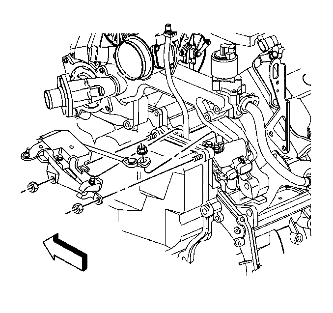
- Disconnect the shift cable from the shift linkage.
- Remove the shift linkage assembly from the transmission.
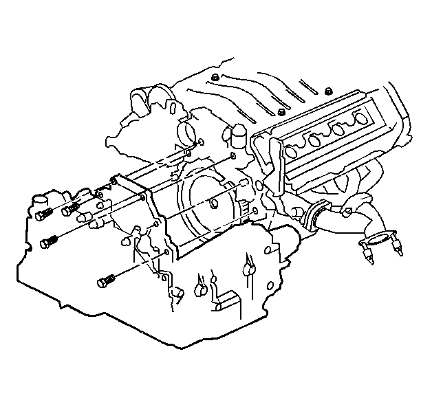
- Remove the upper transmission to engine bolts (2).
- Install the J 28467-B .
- Raise the left side of the powertrain (the transmission side) 25.4 mm (1.0 in) above the powertrain resting position with the adjusting screws.
- Raise the vehicle. Refer to Lifting and Jacking the Vehicle in General Information.
- Support the vehicle with safety stands.
- Remove both front tires and wheels.
- Remove the lower slash shield.
- Remove both front suspension position sensors links from the lower control arms and position out of the way.
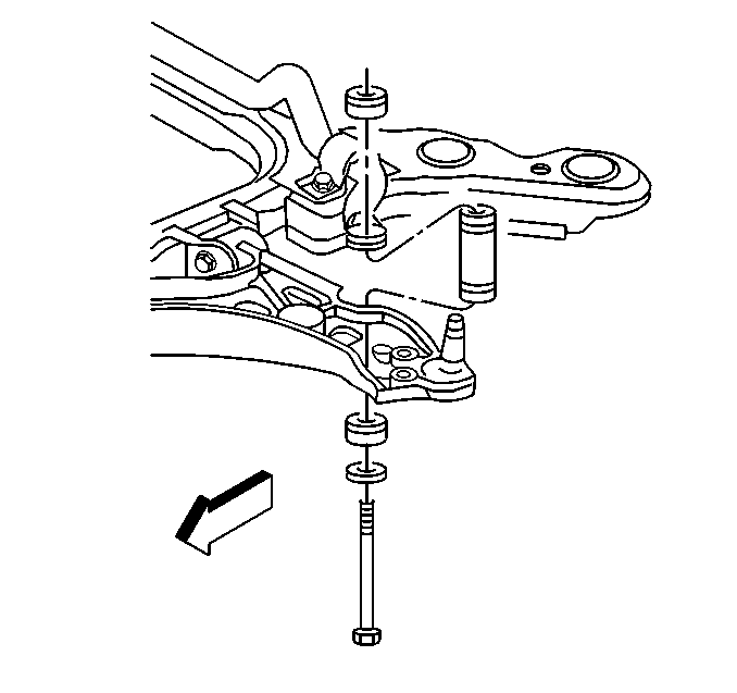
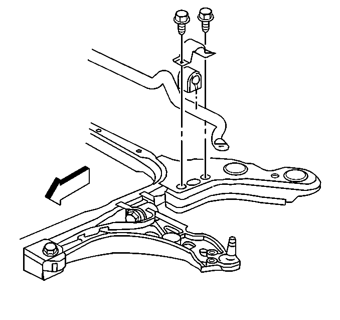
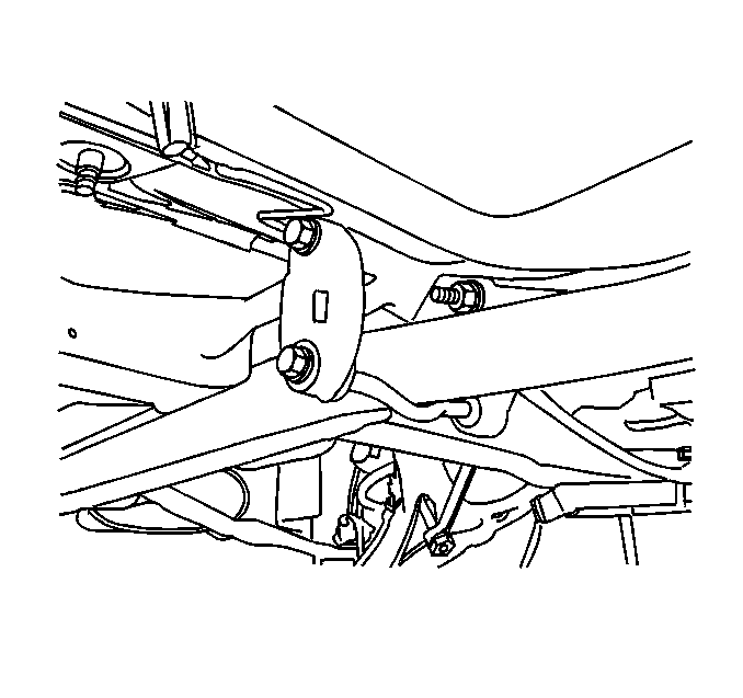
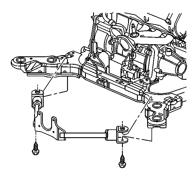
- Remove both stabilizer links from the lower control arms. Allow the stabilizer shaft to sit loosely on the engine frame.
- Remove both stabilizer shaft insulator brackets from the engine frame.
- Remove both drive axle nuts and separate both drive axles from the hubs.
- Remove both tie rod cotter pins and nuts and separate both tie rods from the steering knuckles.
- Remove both lower ball joint cotter pins and nuts. Separate both ball joints from the steering knuckles.
- Remove both drive axles from the transmission.
- Remove the Brake Pressure Modulator Valve (BPMV) and bracket from the engine frame and support with safety wire.
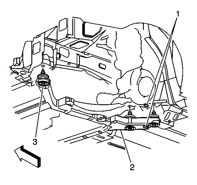
- Remove the rear transmission mount bracket nut (2) and bolts (3).
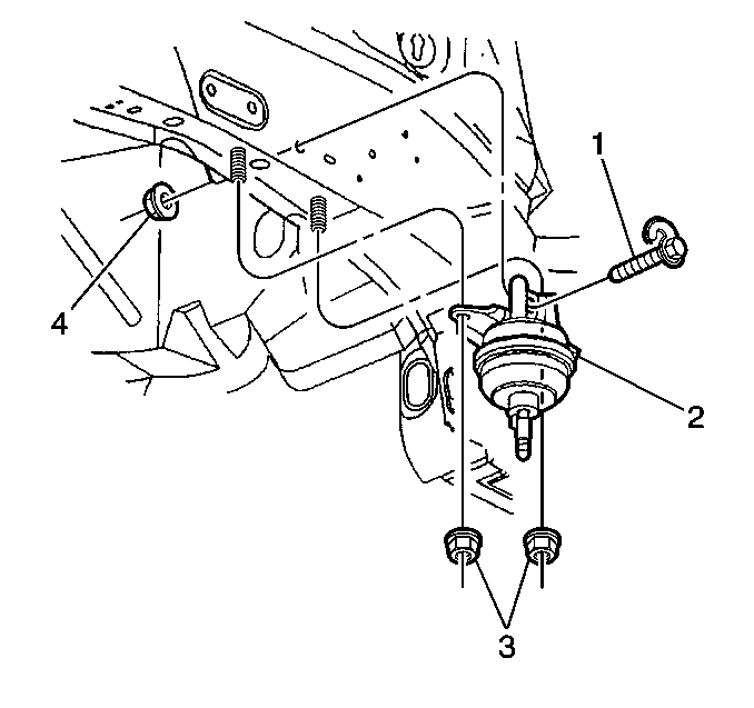
- Remove the rear transmission mount bolt (1) and nuts (3) from the left frame rail.
- Remove the left engine mount nut from the engine frame.
- Remove the right engine mount nuts from the engine frame.
- Remove the steering rack bolts from the engine frame.
- Remove the brake line and power steering line fasteners from the engine frame.
- Remove the post oxygen sensor heat shield and disconnect the post oxygen sensor.
- Disconnect one center exhaust hanger to allow easy movement of the exhaust in the rearward direction.
- Remove the catalytic converter brace.
- Lower the vehicle and support the engine frame using the J 39580 .
- Remove the six engine frame mount bolts (3) from the engine frame (2).
- Fully separate the tie rod ends and lower ball joints from the steering knuckles.
- Raise the vehicle slowly away from the engine frame.
- Remove the engine frame and support table from under the vehicle.
- Remove the steering rack heat shield from the rack.
- Disconnect the power steering lines from the steering rack.
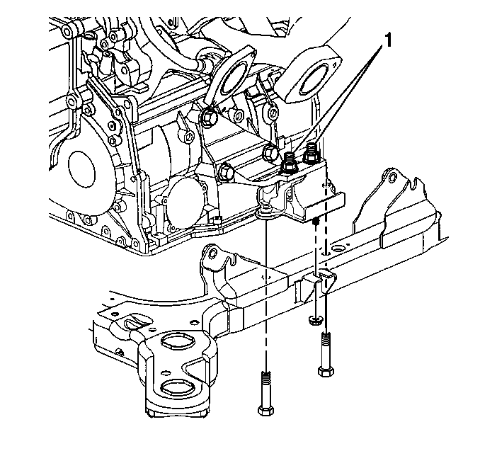
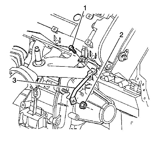
- Remove the right rear engine to transmission bracket upper bolt (1), nuts (3), and bracket (2).
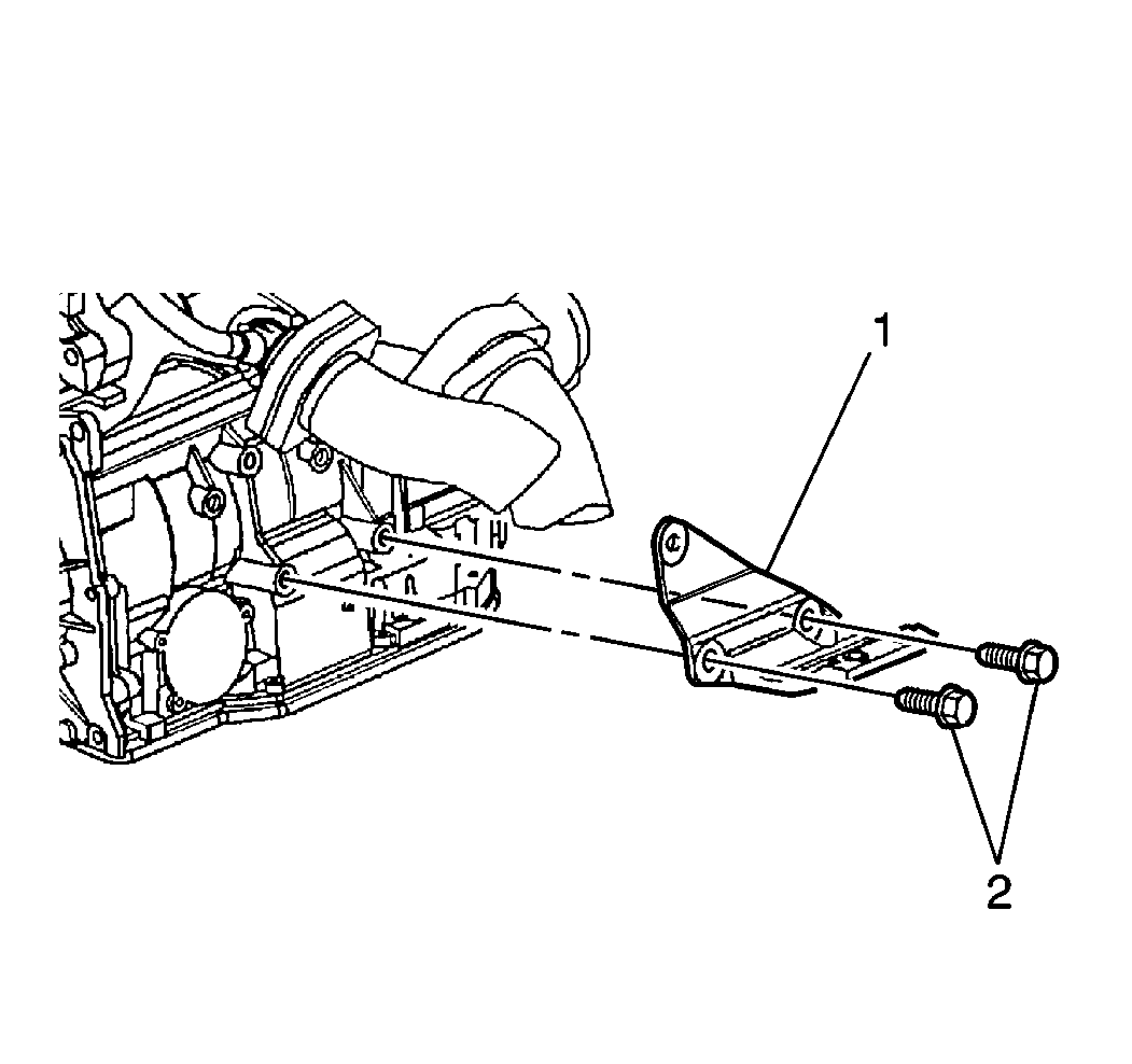
- Remove the right transmission mount bracket lower bolts (2) and bracket (1) from the transmission. It will be necessary to support the steering rack in a position that allows access to the bracket bolts.
- Remove the steering rack from the vehicle.
- Remove the right front engine to transmission brace bolt (1), nut (2), brace (3) and heatshield.
- Remove the right front engine to transmission bracket.
- Remove the engine oil pan to transmission bracket.
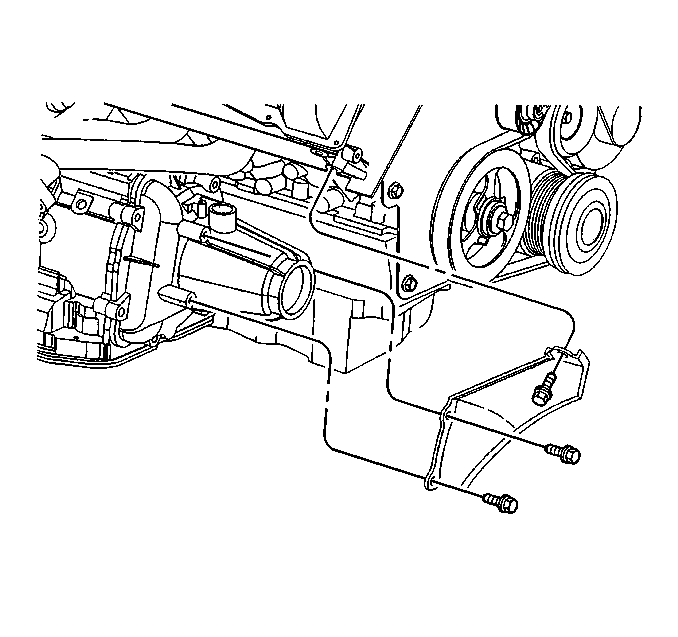
- Remove the torque converter cover brace.
- Remove the torque converter cover.
- Remove the flywheel to converter bolts.
- Disconnect all transmission electrical connectors.
- Remove the engine to transmission heat shield and the bracket.
- Support the transaxle using the J 41160 and a suitable transmission jack.
- Secure the J 41160 to the transaxle.
- Remove the engine to transmission bolts.
- Separate the transmission from the engine.
- Lower the transmission.
- Flush the transmission oil cooler and pipes. Refer to Transmission Fluid Cooler Flushing and Flow Test .
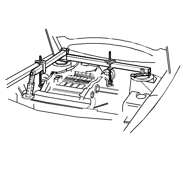
Important : Load the support fixture by tightening the wing nuts several turns in order to take the weight of the powertrain off of the mounts and the frame.



Important: Mark the flywheel to converter position so that they can be assembled in the same position.

Installation Procedure
- Install the rear transmission mount bracket (1) onto the stud before the transmission is fully up into the vehicle
- Loosely attach the rear transmission mount (2) to the left frame rail with the nuts (3) and the bolt (1).
- Raise the transmission on the transmission jack.
- Install the engine to transmission bolts.
- Remove the transmission jack and the J 41160 .
- Install the right front engine to transmission heat shield and brace.
- Install the right front engine to transmission bracket.
- Install the right transmission mount bracket (1) and the lower bolts (2) to the transmission.
- Loosely position the steering rack into the vehicle and insert the tie rod ends into the steering knuckles.
- Install the right rear engine to transmission bracket (2).
- Connect the power steering lines to the power steering rack.
- Install the power steering rack heat shield.
- Install the flywheel to converter bolts.
- Install the torque converter cover.
- Install the following electrical connectors:
- Install both drive axles into the hubs and both drive axle nuts.
- Position the engine frame on to the J 39580 .
- Position the stabilizer bar onto the engine frame in its approximate position.
- Lower the vehicle to the engine frame while locating all the mounting points.
- Install the engine frame mounting bolts finger tight .
- Raise the vehicle away from the J 39580 .
- Tighten the engine frame bolts.
- Install the steering intermediate shaft to the steering gear and install the clamp bolt.
- Install the steering gear bolts.
- Install the left and right transmission mount nuts and the right engine mount nuts at the frame.
- Install both lower ball joints into the steering knuckles and both ball joint nuts and cotter pins.
- Tighten the ball joint nut to 10 N·m (84 Ib in)
- Tighten the nut an additional 120 degrees.
- Tighten the tie rod end nut to 10 N·m (7.5 Ib ft) then an additional 1/3 turn (2 flats).
- Install the brake and power steering line retainers to the engine frame.
- Install the brake pressure modulator valve and bracket to the engine frame.
- Install the sway bar insulators onto the sway bar.
- Install both stabilizer links to the control arms.
- Install both front suspension position sensors to the lower control arms.
- Install lower close out panel.
- Install the catalytic converter brace.
- Connect the center exhaust hanger.
- Connect the post oxygen sensor and install the heat shield.
- Lower the vehicle.
- Install both front tire and wheel assemblies. Refer to Tire and Wheel Removal and Installation in Tires and Wheels.
- Remove the J 28467-B .
- Install the upper bell housing bolts.
- Install the transmission cooler pipe fittings at the transmission.
- Install the transmission oil sending pipe to the transmission.
- Install the shift linkage assembly to the transmission.
- Install the shift cable to the shift linkage.
- Connect surge tank outlet hose. Refer to Surge Tank Pipe Replacement - Outlet in Engine Cooling.
- Connect the surge tank inlet hose. Refer to Surge Tank Pipe Replacement - Inlet in Engine Cooling.
- Install the air cleaner assembly. Refer to Air Cleaner Assembly Replacement in Engine Controls.
- Install the upper filler panel.
- Connect the negative battery cable. Refer to Battery Negative Cable Disconnection and Connection in Engine Electrical.
- Fill the cooling system. Refer to Cooling System Draining and Filling in Engine Cooling.
- Bleed the power steering system. Refer to Power Steering Gear and Pump in Steering.
- Add DEXRON-III transmission fluid as required. Refer to Specifications.
- Check the front suspension alignment, adjust the toe as necessary.
- Reset the transmission adapts. Refer to Resetting Transmission Adapts.


| 3.1. | Guide the rear mount bracket and the rear mount together as the transmission is raised into the vehicle. |
| 3.2. | Align the transmission with the engine and position the transmission onto the engine dowels. |

Tighten
Tighten the bolts to 75 N·m (55 Ib ft).

Tighten
Tighten the bolts to 50 N·m (37 Ib ft).

Tighten
Tighten the bolts to 50 N·m (37 Ib ft).

Tighten
Tighten the bolts (2) to 110 N·m (81 Ib ft).

Tighten
Tighten the bolt (1) to 110 N·m (81 Ib ft) and the
nuts (3) to 50 N·m (37 Ib ft).
Tighten
Tighten the lines to 27 N·m (20 Ib ft).
Important: Line up the flywheel and converter using the alignment marks made at disassembly.
Tighten
Tighten the bolts to 60 N·m (44 Ib ft).
| • | The transmission connectors. |
| • | The VSS connector. |
| • | The ground junction block. |
Tighten
Tighten the nuts to 145 N·m (110 Ib ft).
Tighten
Tighten the engine frame bolts to 192 N·m (142 Ib ft).
Tighten
Tighten the clamp bolt to 50 N·m (37 Ib ft).
Tighten
Tighten the bolts to 105 N·m (77 Ib ft).
Tighten
Tighten the nuts to 50 N·m (37 Ib ft).
Important: When tightening the ball joint nut, a minimum torque of 50 N·m (37 Ib ft) must be obtained. If 50 N·m(37 Ib ft) is not obtained, inspect for stripped threads. If threads are satisfactory, replace the ball joint and knuckle. If required, turn the nut up to an additional 60 degrees to allow for installation of the cotter pin.
Tighten
Important: When tightening the tie rod end nut, a minimum torque of 45 N·m (33 Ib ft) must be obtained. If 45N·m (33 Ib ft) is not obtained, inspect for stripped threads. If the threads are satisfactory, replace the tie rod end and knuckle.
After tightening the castellated nut to specification, align the slot in the nut to the cotter pin hole by tightening only. Do not loosen the nut for cotter pin installation.
Tighten the tie rod end nut to 100 N·m (74 Ib ft) then an additional 1/3 turn (2 flats).
Tighten
Tighten the nuts to 65 N·m (49 Ib ft).


Tighten
Tighten the cooler pipe fittings at transmission to 22 N·m (16 Ib ft).


