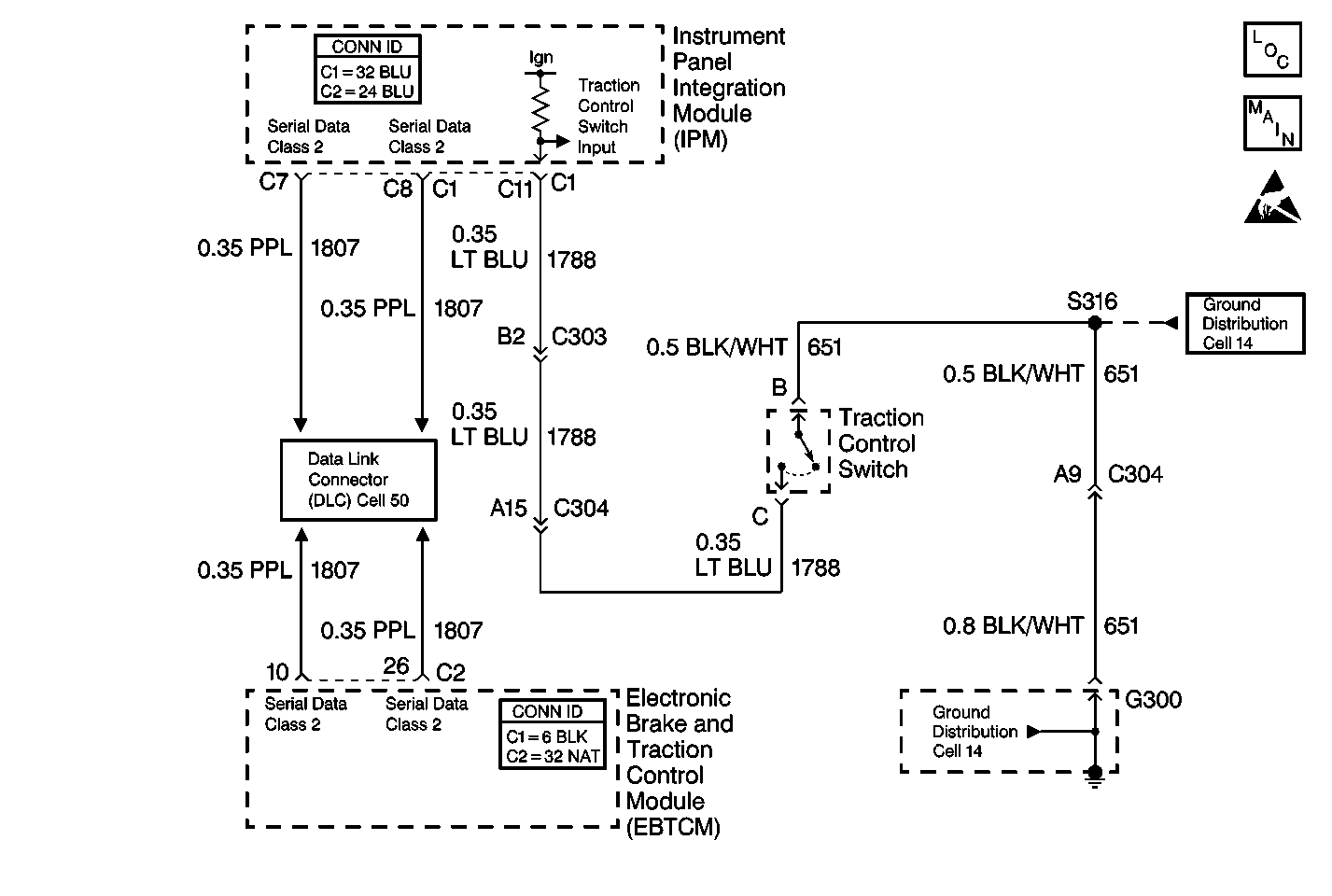
Circuit Description
The TRACTION OFF message is controlled by the EBTCM. When the IPM sees the Traction Control Disable Input grounded through the momentary traction control disable switch, it sends a Class 2 message to the EBTCM that tells the EBTCM that the traction control disable switch has been pressed. The EBTCM then disables Traction Control and sends a message to the instrument cluster (IPC) to turn the TRACTION OFF message on. Each time the ignition switch is cycled OFF to ON, Traction Control is enabled.
Diagnostic Aids
| • | It is very important that a thorough inspection of the wiring and connectors be performed. Failure to carefully and fully inspect wiring and connectors may result in misdiagnosis, causing part replacement with reappearance of the malfunction. |
| • | An intermittent malfunction can be caused by poor connections, broken insulation, or a wire that is broken inside the insulation. |
| • | If an intermittent malfunction exists, refer to Intermittents and Poor Connections Diagnosis in Wiring Systems. |
Test Description
The numbers below refer to step numbers on the diagnostic table.
-
Checks if the traction control disable switch is open or inoperative.
-
Checks for an open in CKT 651.
-
Checks for an open in CKT 1788.
Step | Action | Value(s) | Yes | No |
|---|---|---|---|---|
1 | Did you perform the ABS Diagnostic System Check? | -- | Go to Step 2 | |
Is the resistance less than the specified value? | 5 ohms | Go to Step 4 | Go to Step 3 | |
3 | Replace the traction control switch. Refer to Electronic Traction Control Switch Replacement . Did you complete the repair? | -- | -- | |
Does the scan tool indicate that the traction control switch is On? | -- | Go to Step 5 | Go to Step 6 | |
5 | Repair the open in CKT 651. Refer to Wiring Repairs in Wiring Systems. Did you complete the repair? | -- | -- | |
Is the resistance less than the specified value? | 5 ohms | Go to Step 8 | Go to Step 7 | |
7 | Repair the open in CKT 1788. Refer to Wiring Repairs in Wiring Systems. Did you complete the repair? | -- | -- | |
8 | Replace the IPM. Refer to Body Control Module Replacement in Body Control System. Did you complete the repair? | -- | -- |
