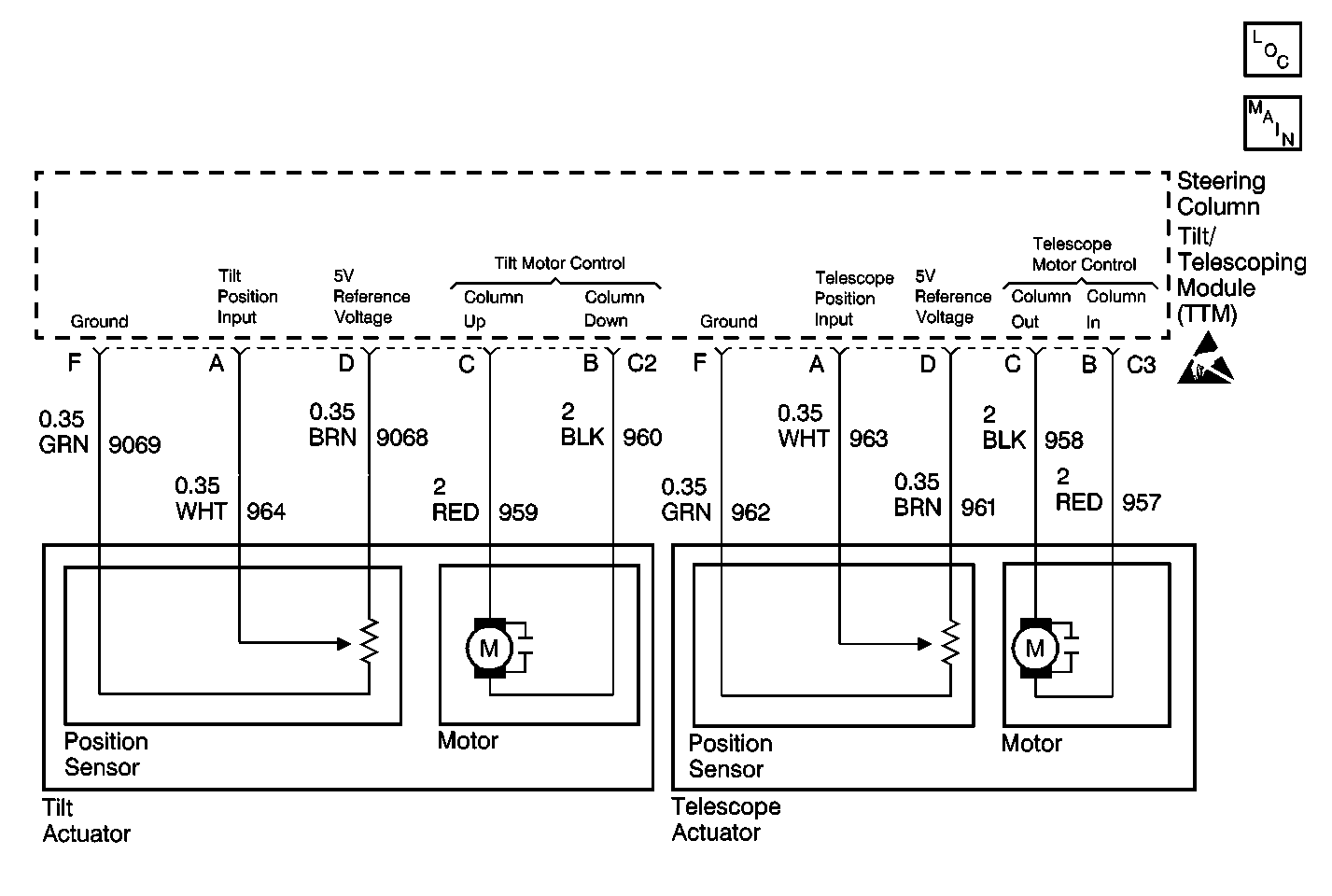
Circuit Description
The steering column tilt/telescoping module (TTM) receives inputs from the tilt position sensor during memory recall, memory set, and easy exit functions. The potentiometer in the tilt position sensor varies in resistance as the motor moves the steering column up or down. The TTM receives a variable voltage input depending on the resistance of the potentiometer. During memory set, the TTM records the voltage across the tilt position sensor potentiometer. During memory recall, the TTM moves the tilt motor until the voltage across the potentiometer matches the voltages stored in memory. For the easy exit function, the TTM moves the tilt motor until the voltage matches what the TTM has recorded in memory for the easy exit. During normal operation, the tilt position sensors are checked against out-of-range limits.
Conditions for Setting the DTC
| • | The TTM sets DTC B2882 any time it detects the tilt position sensor input voltage is out-of-range. |
| • | DTC B2882 sets only if DTC TTM B1982 or DTC TTM B1983 is not current. |
Action Taken When the DTC Sets
When DTC B2882 is set as current, the steering column tilt/telescoping module (TTM) disables the tilt motor during memory recall or easy exit operations. The tilt motor remains enabled for manual positioning.
Conditions for Clearing the DTC
| • | The TTM detects that the tilt position sensor input is within the valid voltage range. |
| • | Use the On-Boards clearing DTCs feature. |
| • | Use a scan tool. |
Test Description
The numbers below refer to the step numbers on the diagnostic table:
-
Perform the Tilt/Telescoping Steering Column Diagnostic System Check before continuing with the diagnosis of this DTC.
-
Determines whether the failure is in the steering column tilt/telescoping module (TTM) or the tilt position sensor.
-
Clear all DTCs after the repair procedure is complete.
Step | Action | Value(s) | Yes | No |
|---|---|---|---|---|
Was the Tilt/Telescoping Steering Column Diagnostic System Check performed? | -- | Go to Tilt/Telescoping Steering Column Diagnostic System Check | ||
Is the voltage approx. equal to the specified value? | 5 V | |||
3 |
Is the replacement complete? | -- | -- | |
4 | Replace the tilt actuator. Refer to Tilt Actuator Assembly Replacement - On Vehicle . Is the repair complete? | -- | -- | |
Is the Diagnostic System Check complete? | -- | System OK | -- |
