Removal Procedure
Tools Required
J 38822 Cam Chain Tension Holder
- Remove the left side cam cover. Refer to Camshaft Cover Replacement .
- Remove the right side cam cover. Refer to Camshaft Cover Replacement .
- Secure the camshaft sprockets to the timing chain by installing tie-wraps through the cam sprocket holes. Use four tie-wraps per sprocket.
- Working behind the sprockets, install cam chain holder J 38822 in order to position it between the chain tensioner and the guide. Apply the tension by tightening the tension adjusting screw.
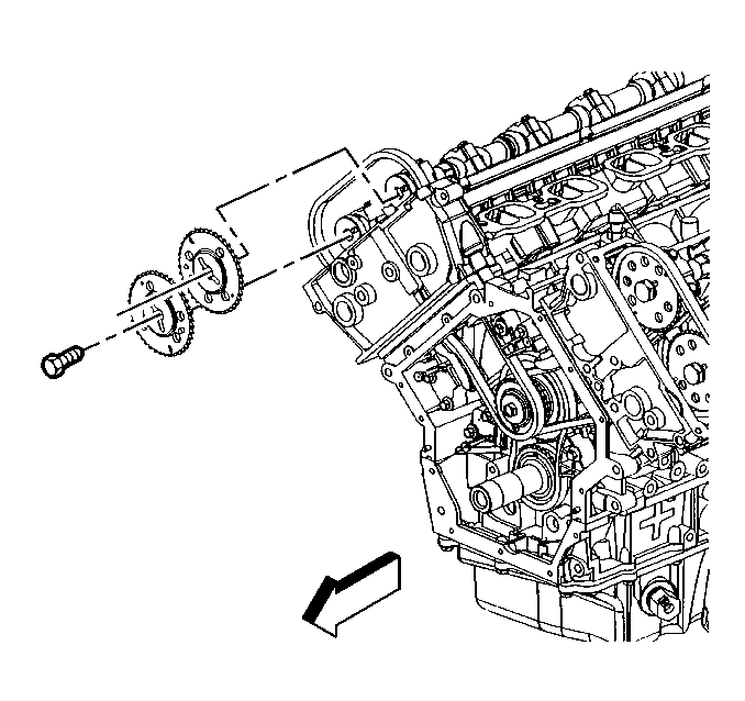
- Remove both cam sprocket bolts.
- Work the sprockets off of the cams using the play in the chain.
- Alternately loosen the cam bearing cap screws a few turns at a time until all valve spring pressure has been released.
- Remove the bolts and the bearing caps.
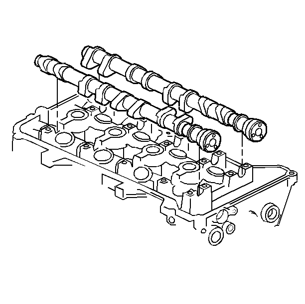
- Remove the camshaft.
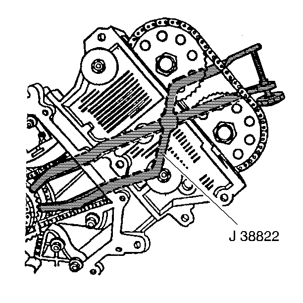
Important: The sprocket/chain relationship must be maintained throughout this procedure or the camshaft timing will be lost. This will require further engine disassembly to retime.
Important: Note the relative location of the cam drive pins in the end of the camshafts.
Important: Whenever removing a camshaft from an engine with a suspected faulty camshaft operation, the camshaft lobes should be visually checked and measured. Refer to Camshaft and Bearings Clean and Inspect .
Installation Procedure
- Apply the camshaft prelube, GM P/N 1052365, to the face of each cam lobe.
- Install the camshaft.
- Position the cam bearing caps to the cylinder head.
- Loosely install the cam bearing cap bolts.
- Tighten the camshaft bearing cap bolts in sequence shown.
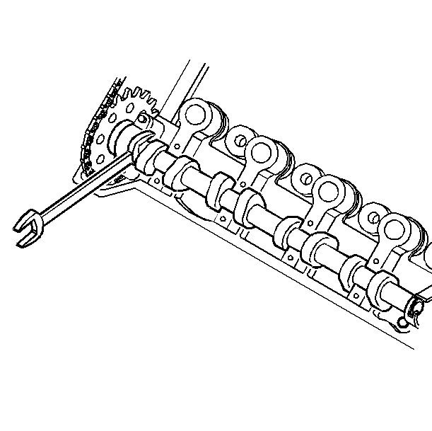
- Using the hex cast into the camshaft, rotate the cams until the drive pins are in position to engage the cam sprockets over the cams.
- Work the cam sprockets over the cams.
- Install the remaining bolts.
- Remove chain holder J 38822 .
- Remove the tie-wraps from the cam sprockets.
- Install the left side cam cover. Refer to Camshaft Cover Replacement .
- Install the right side cam cover. Refer to Camshaft Cover Replacement .


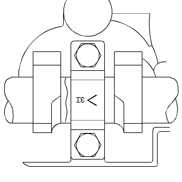
Important:
• Each cap is identified for position and direction. • The arrow points toward the front of the engine. • E indicates a cap for the exhaust cam. • I indicates a cap for the intake cam. • Position 1 is from the front of the engine.
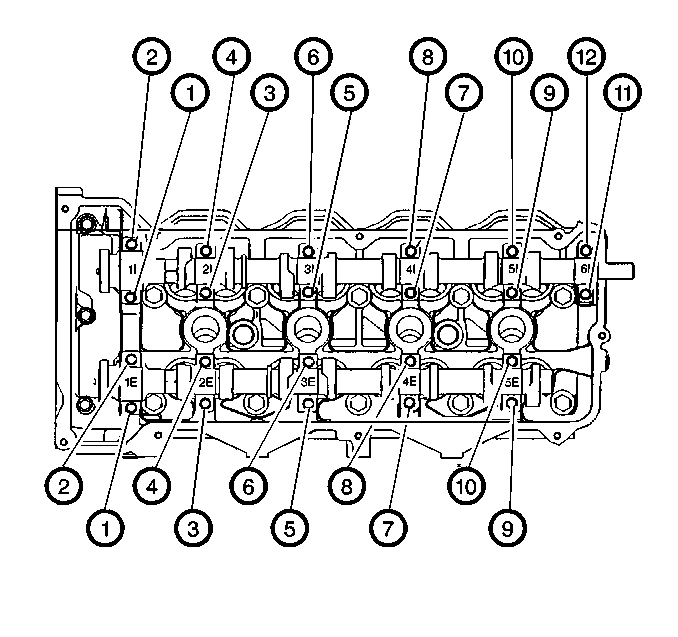
Notice: Use the correct fastener in the correct location. Replacement fasteners must be the correct part number for that application. Fasteners requiring replacement or fasteners requiring the use of thread locking compound or sealant are identified in the service procedure. Do not use paints, lubricants, or corrosion inhibitors on fasteners or fastener joint surfaces unless specified. These coatings affect fastener torque and joint clamping force and may damage the fastener. Use the correct tightening sequence and specifications when installing fasteners in order to avoid damage to parts and systems.
Tighten
Tighten the bearing cap bolts to 5 N·m+ 30 degrees (44 lb in
+ 30 degrees).

Tighten
Tighten the sprocket bolts to 120 N·m (89 lb ft).
