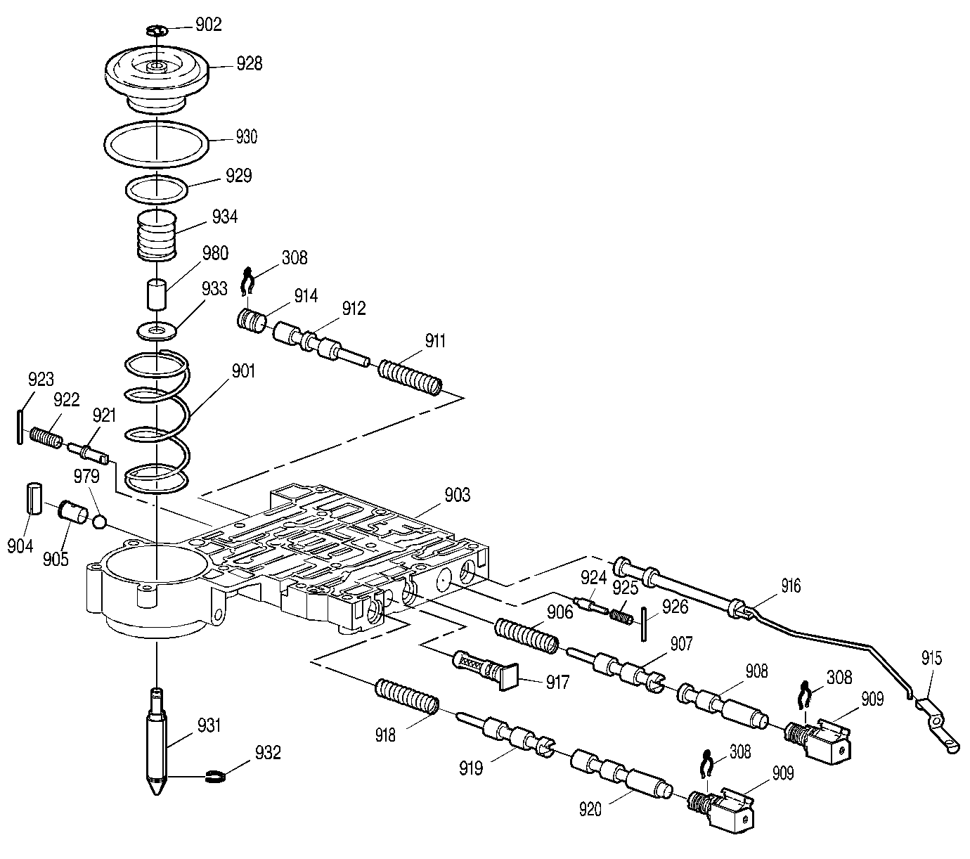
| Figure 1: |
Lower Control Valve Body Assembly
|
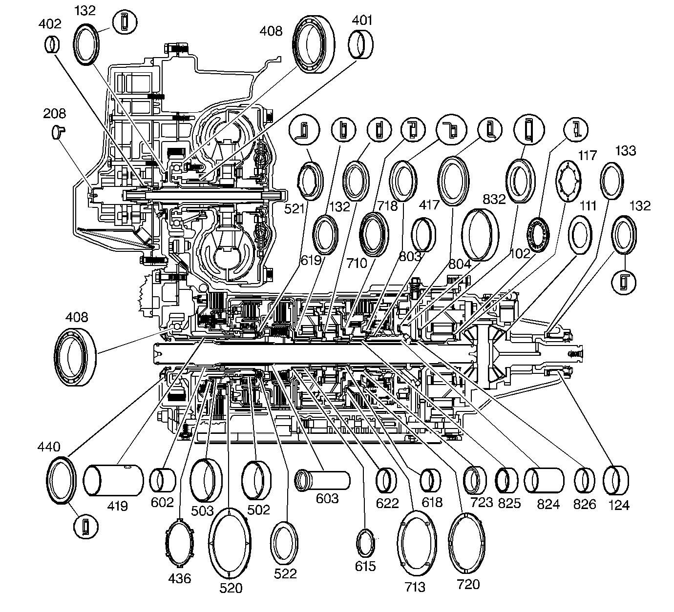
| Figure 2: |
Bushings, Bearings and Washers
|
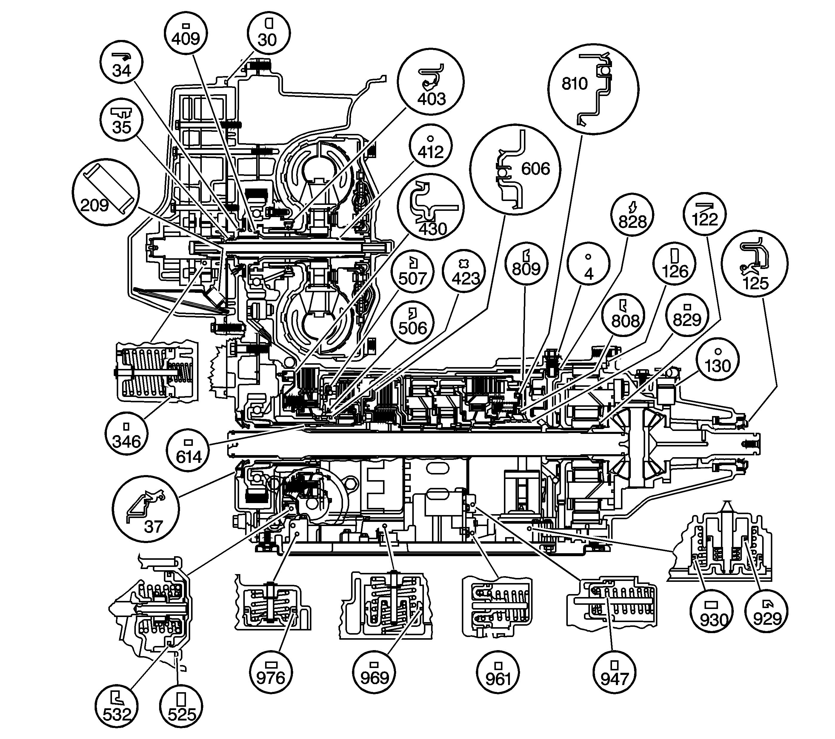
| Figure 3: |
Seals
|
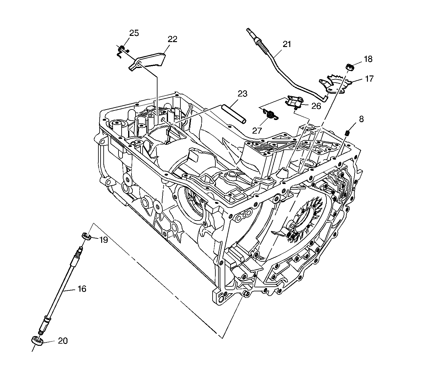
| Figure 4: |
Parking Pawl, Actuator Assembly and Manual Shaft
|
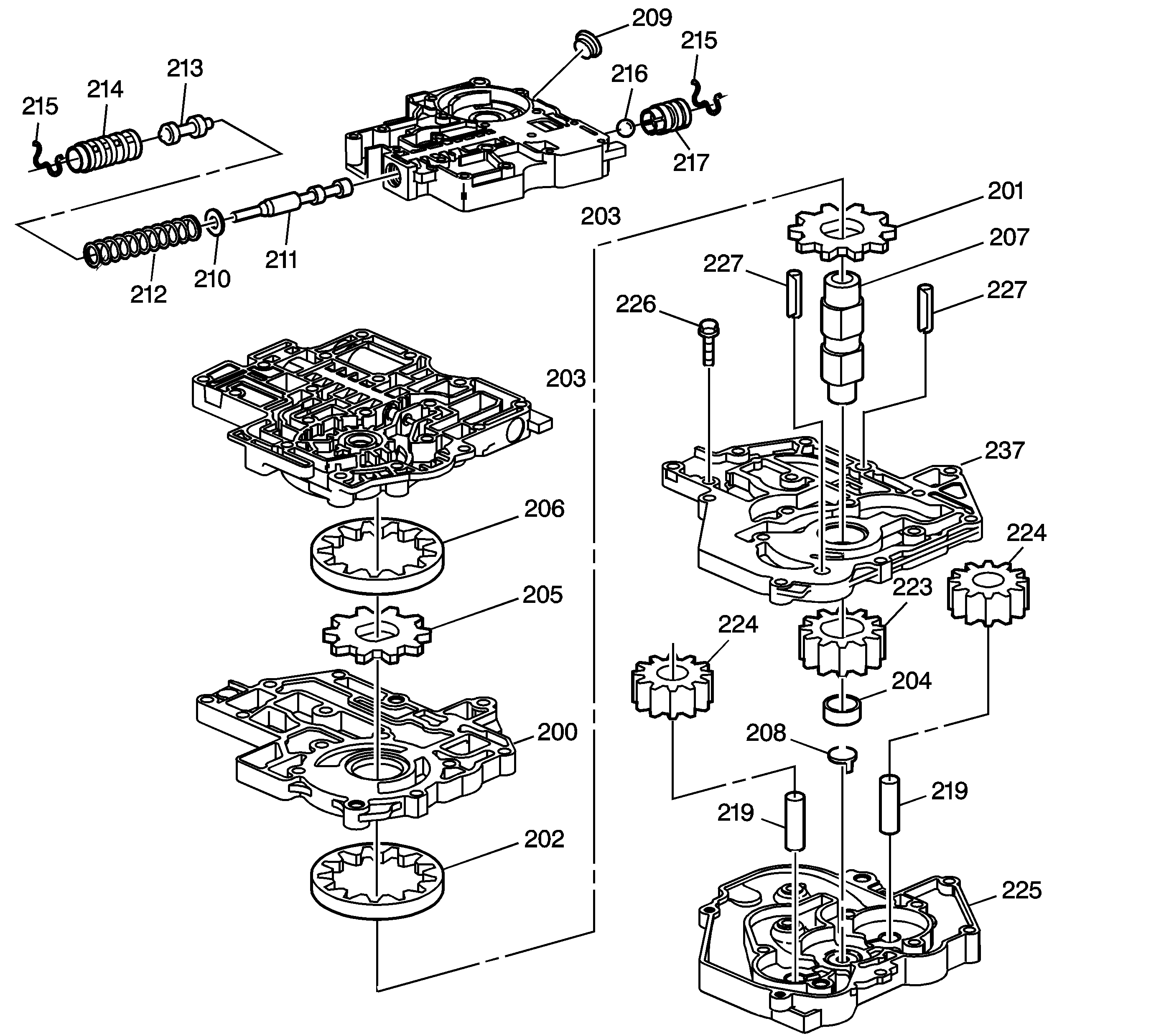
| Figure 5: |
Scavenge, Primary and Secondary Fluid Pump Assemblies
|
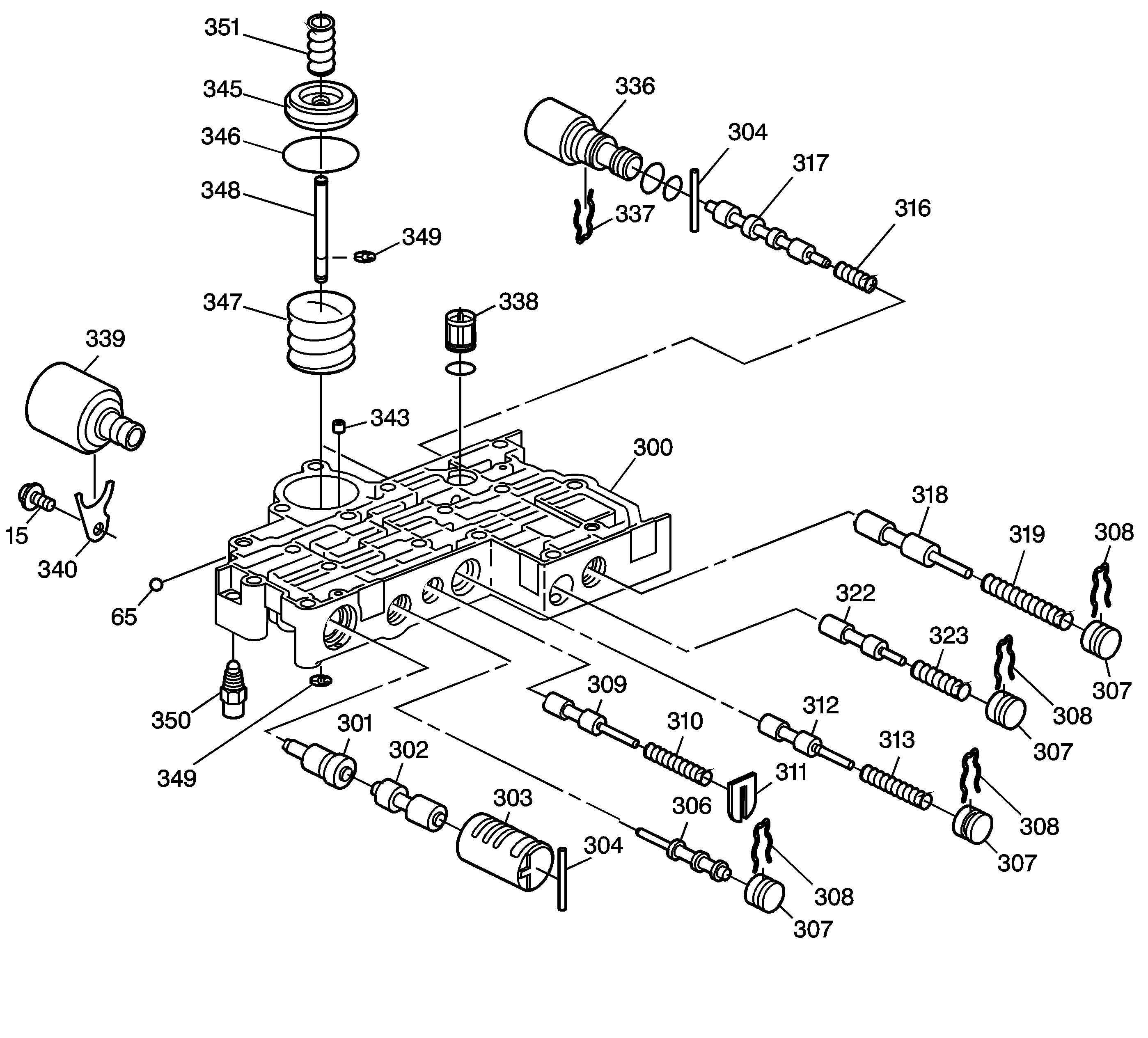
| Figure 6: |
Upper Control Valve Body Assembly
|
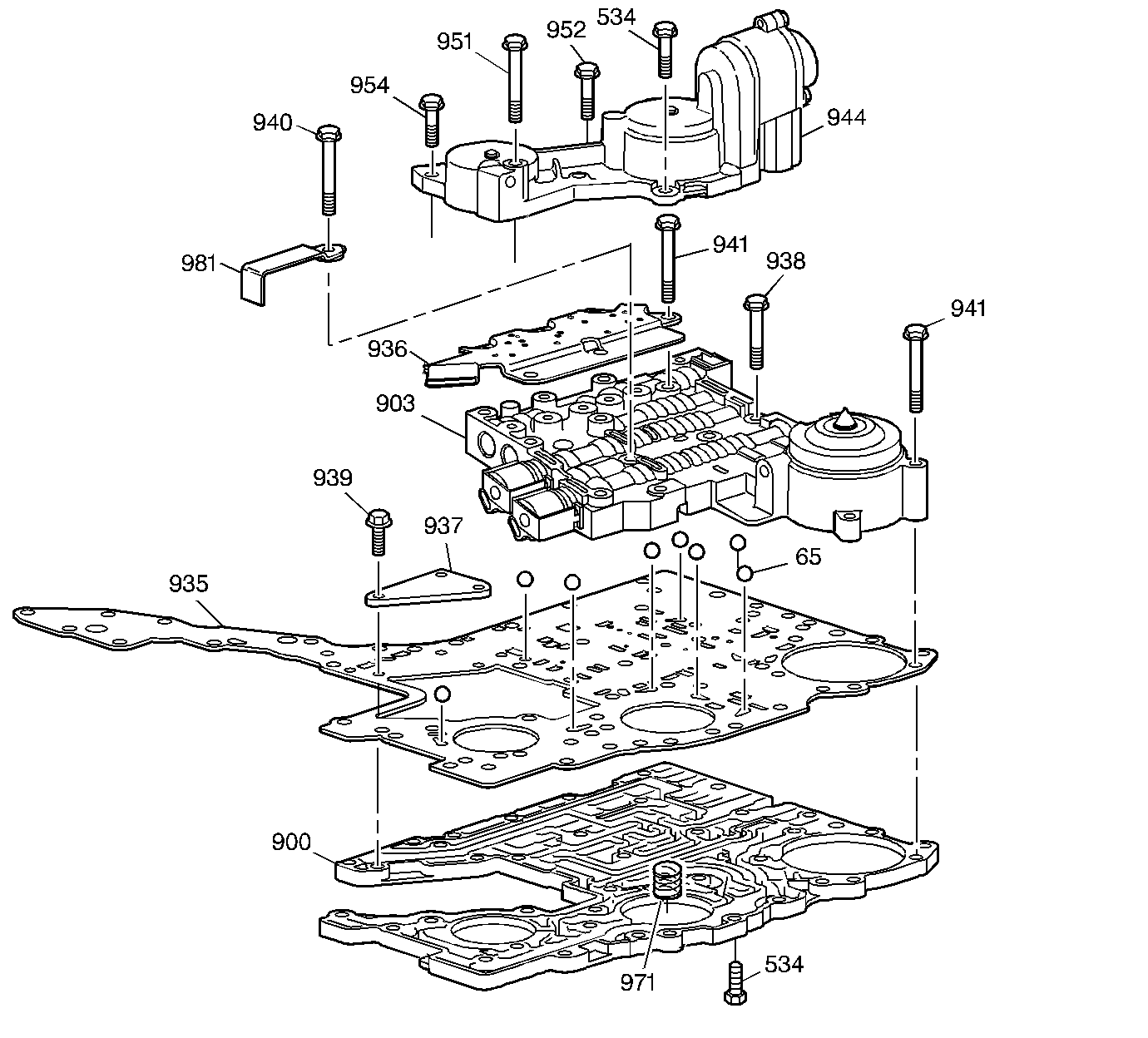
| Figure 7: |
Lower Channel Plate, Control Valve Body and Accumulator Housing Assembly
|
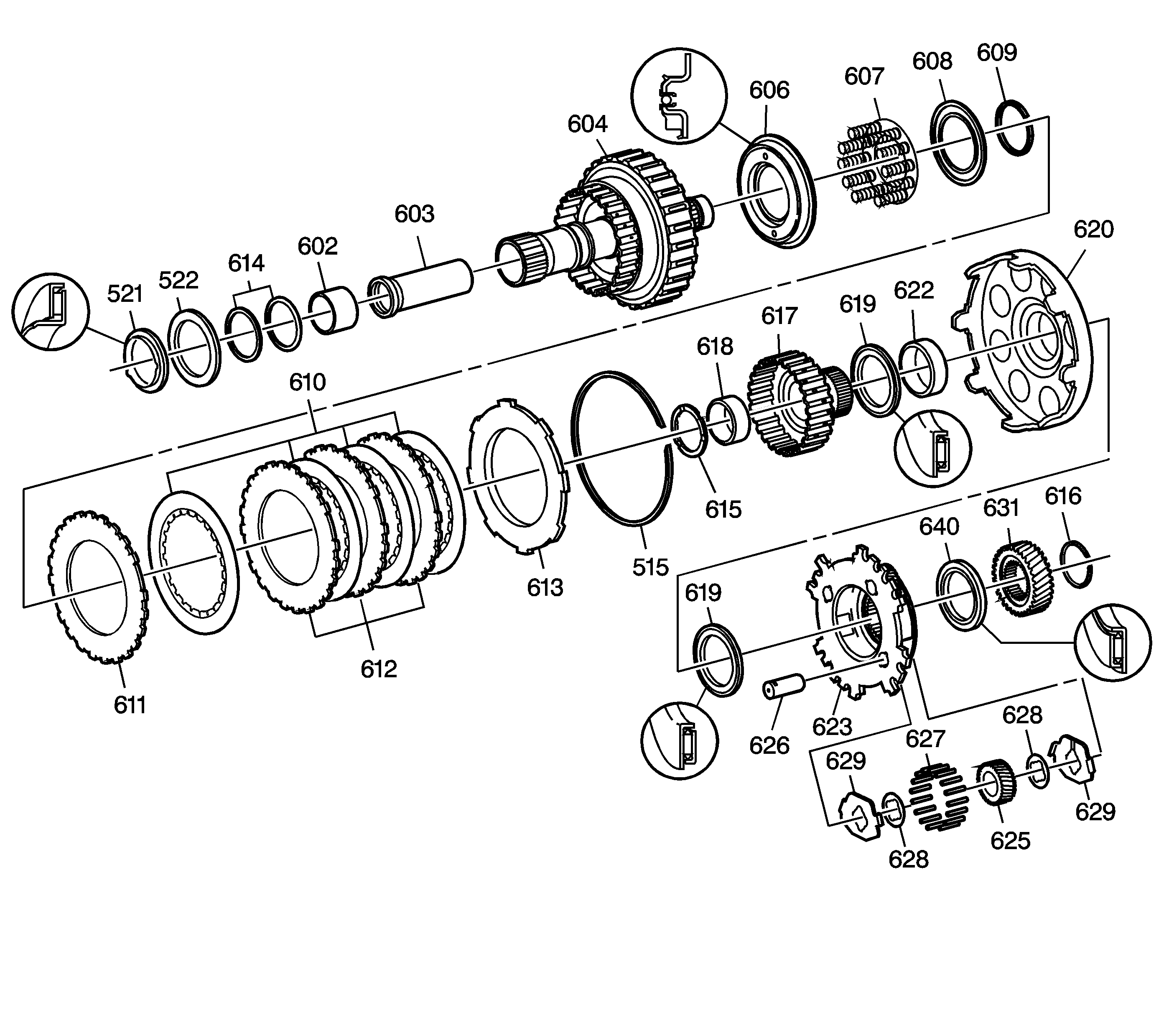
| Figure 8: |
3rd Clutch and Reaction Carrier Assembly
|
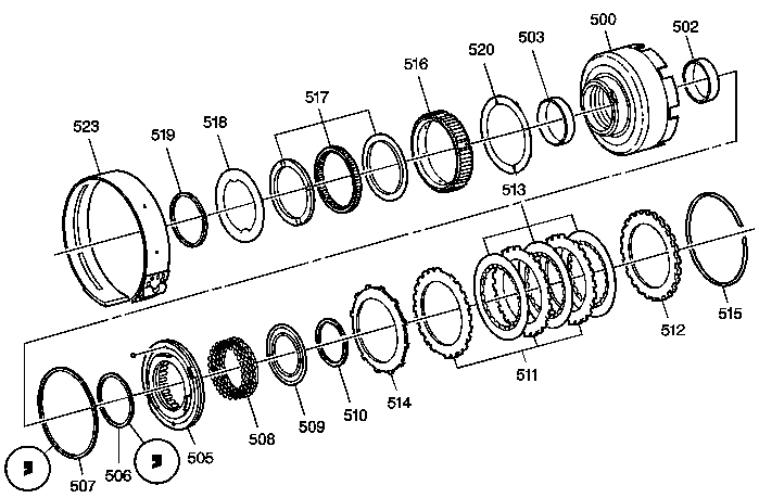
| Figure 9: |
Reverse Clutch and 2nd Sprag Clutch Assemblies
|
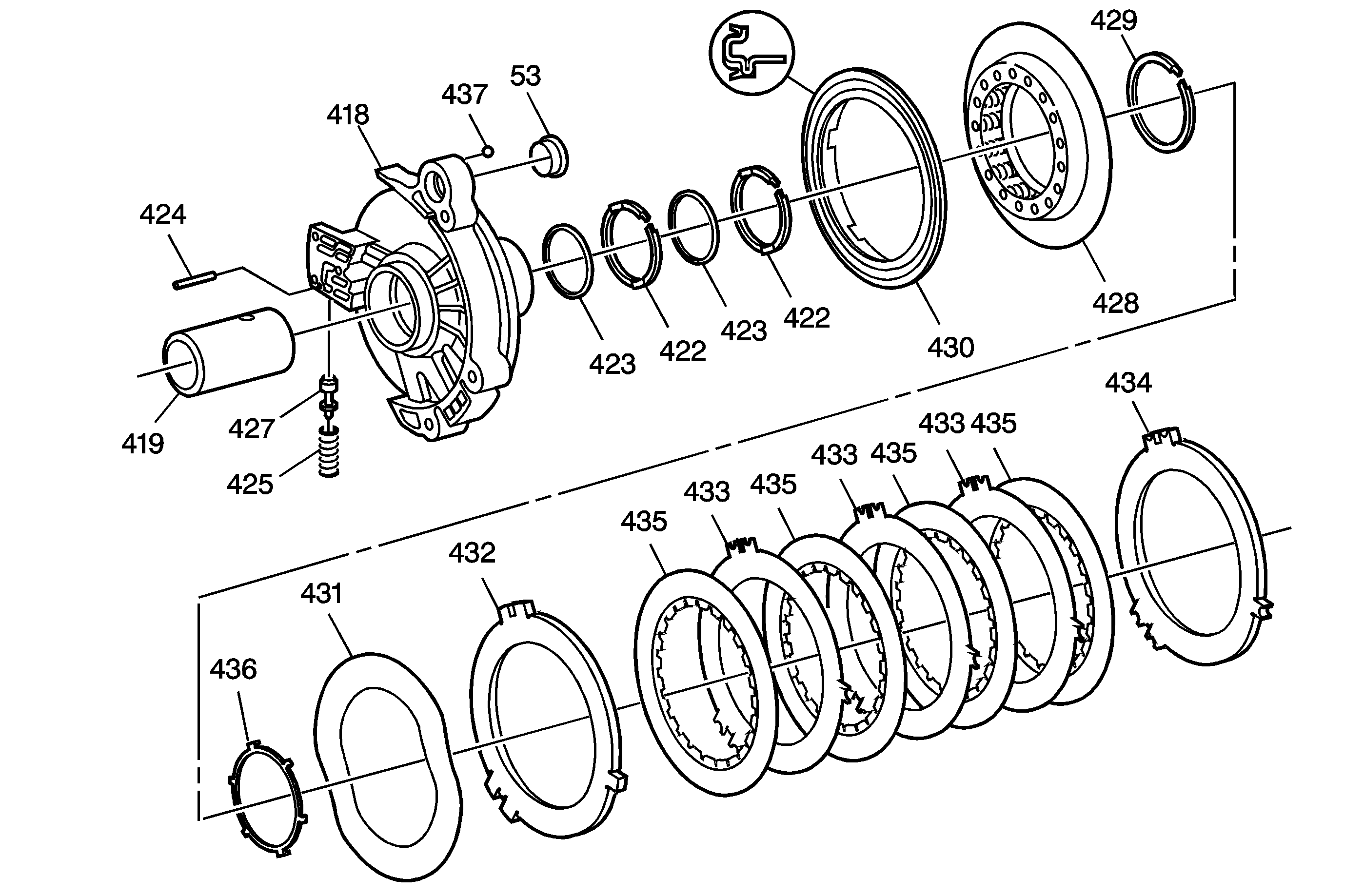
| Figure 10: |
Driven Sprocket Support and 2nd Clutch Assembly
|
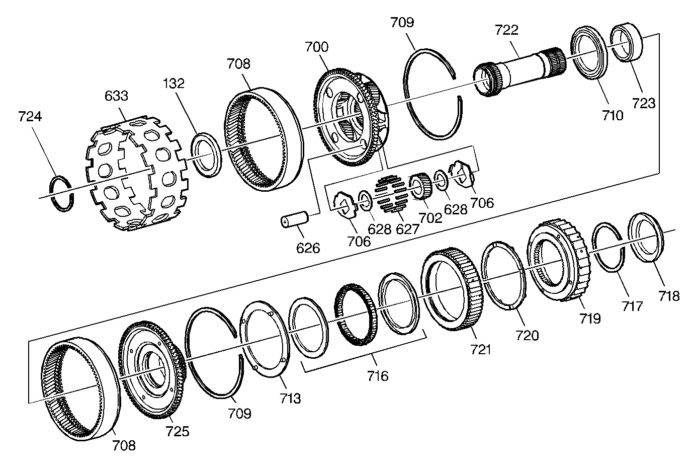
| Figure 11: |
Input Carrier and Forward Sprag Clutch Assemblies
|
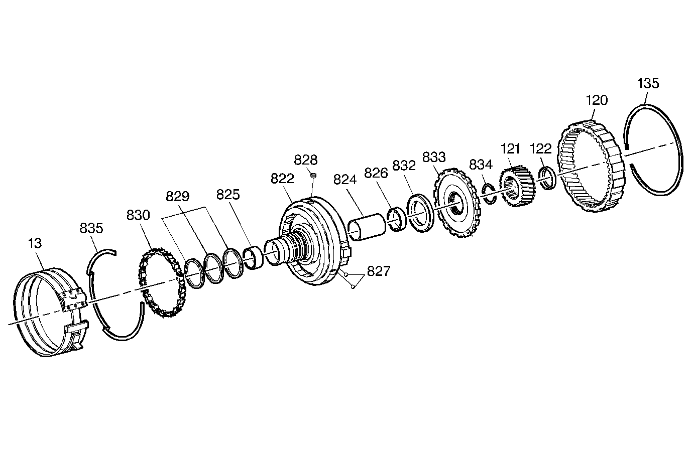
| Figure 12: |
Forward Clutch Support Assembly
|
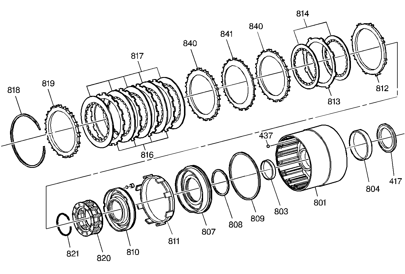
| Figure 13: |
Forward Clutch Assembly
|
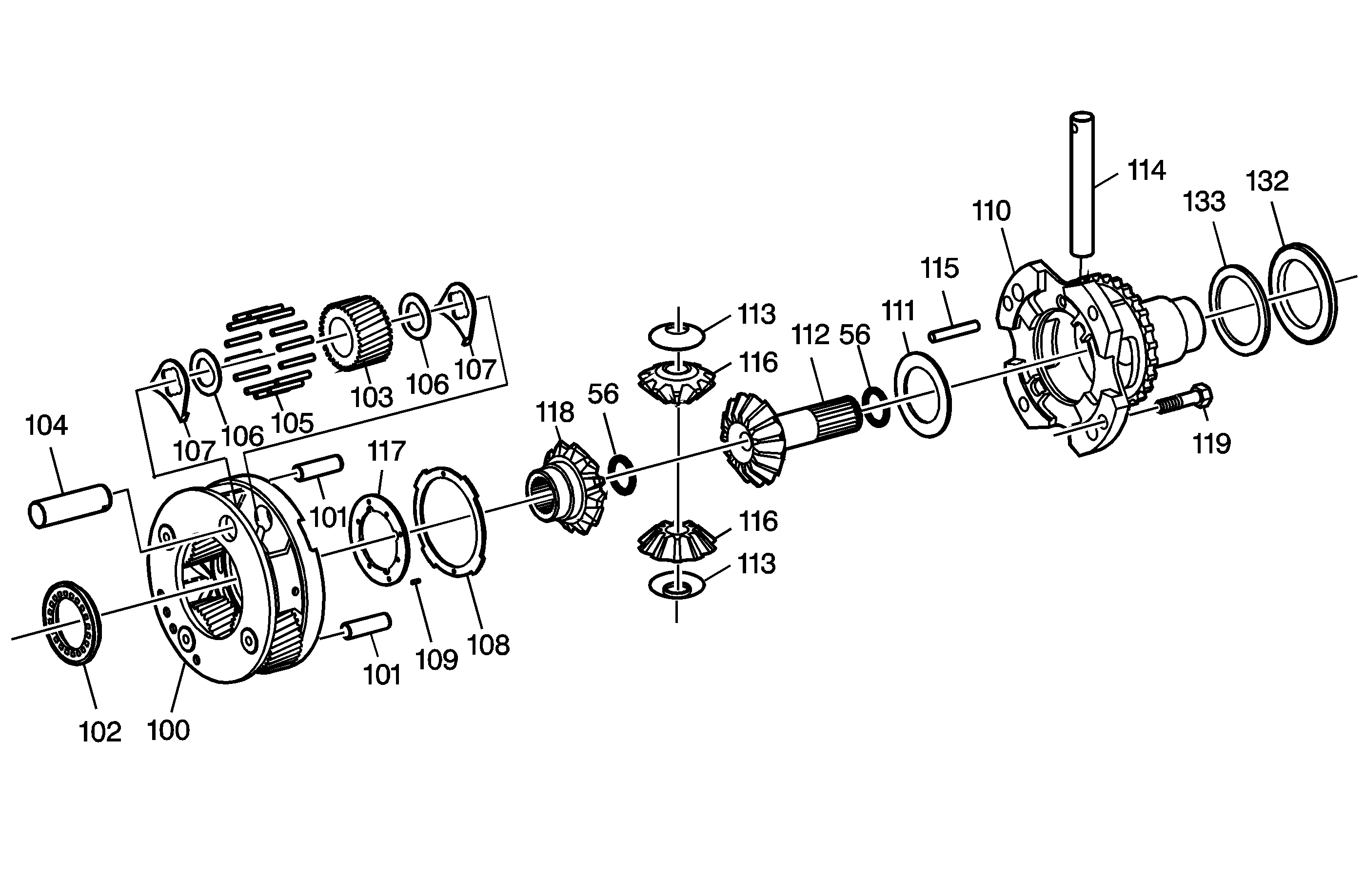
| Figure 14: |
Final Drive Assembly
|
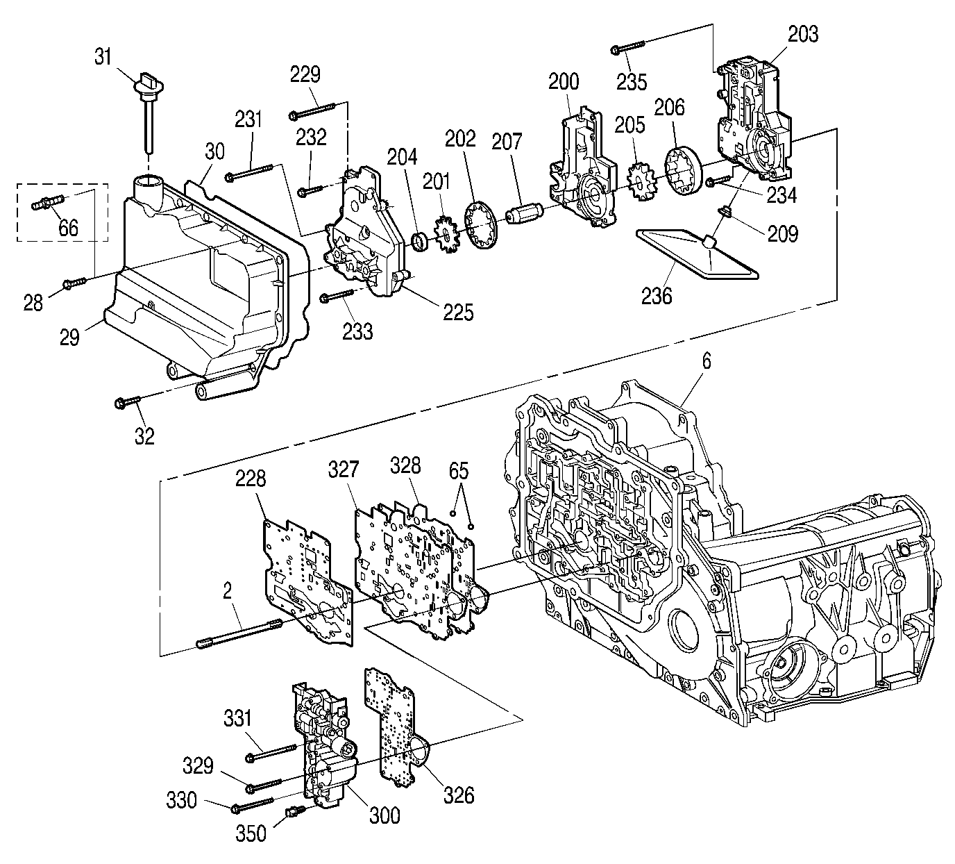
| Figure 15: |
Case and Associated Parts (2 of 3)
|
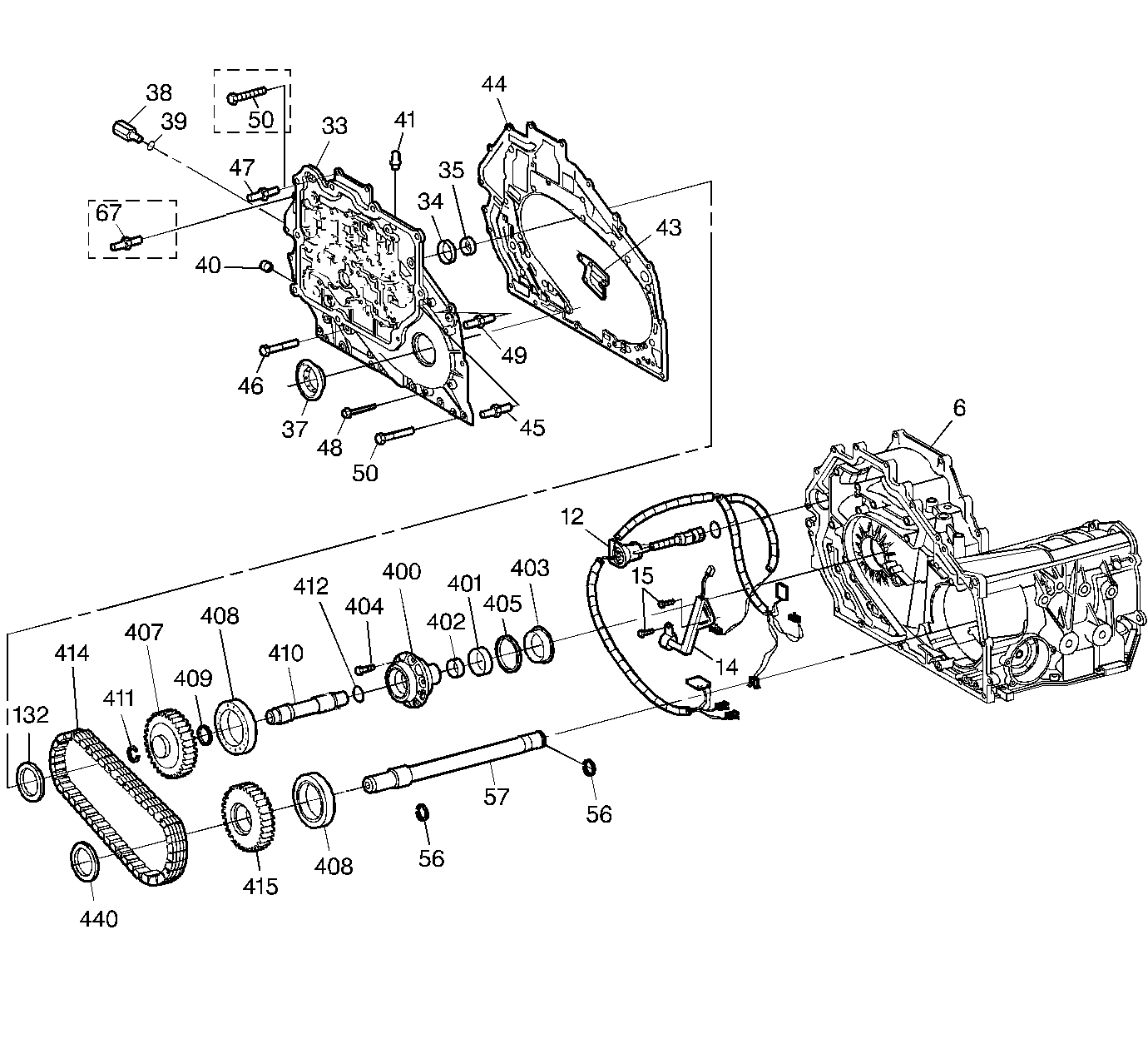
| Figure 16: |
Case and Associated Parts (3 of 3)
|
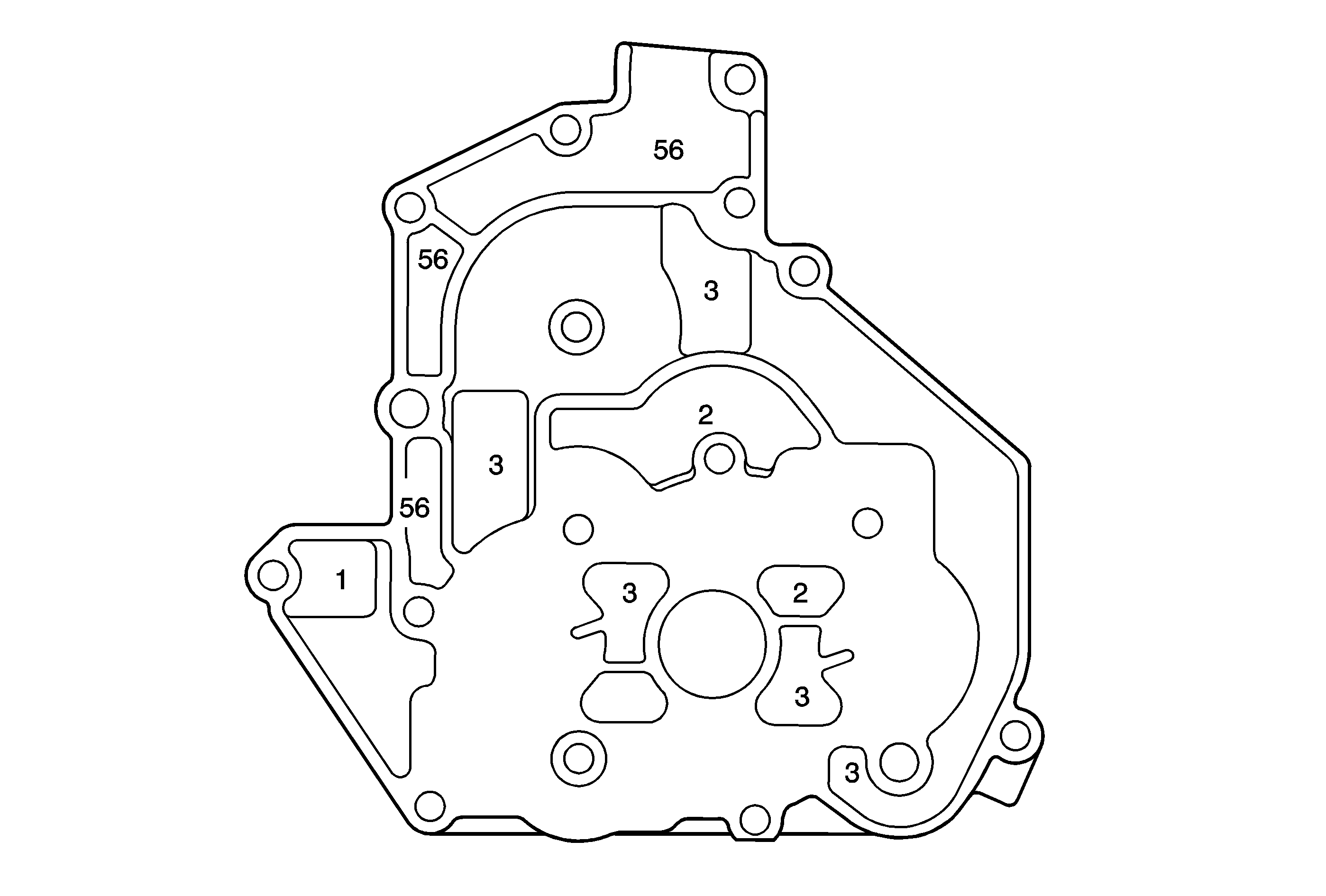
| Figure 17: |
Scavenge Pump Cover Fluid Passages (Scavenge Pump Body Side)
|
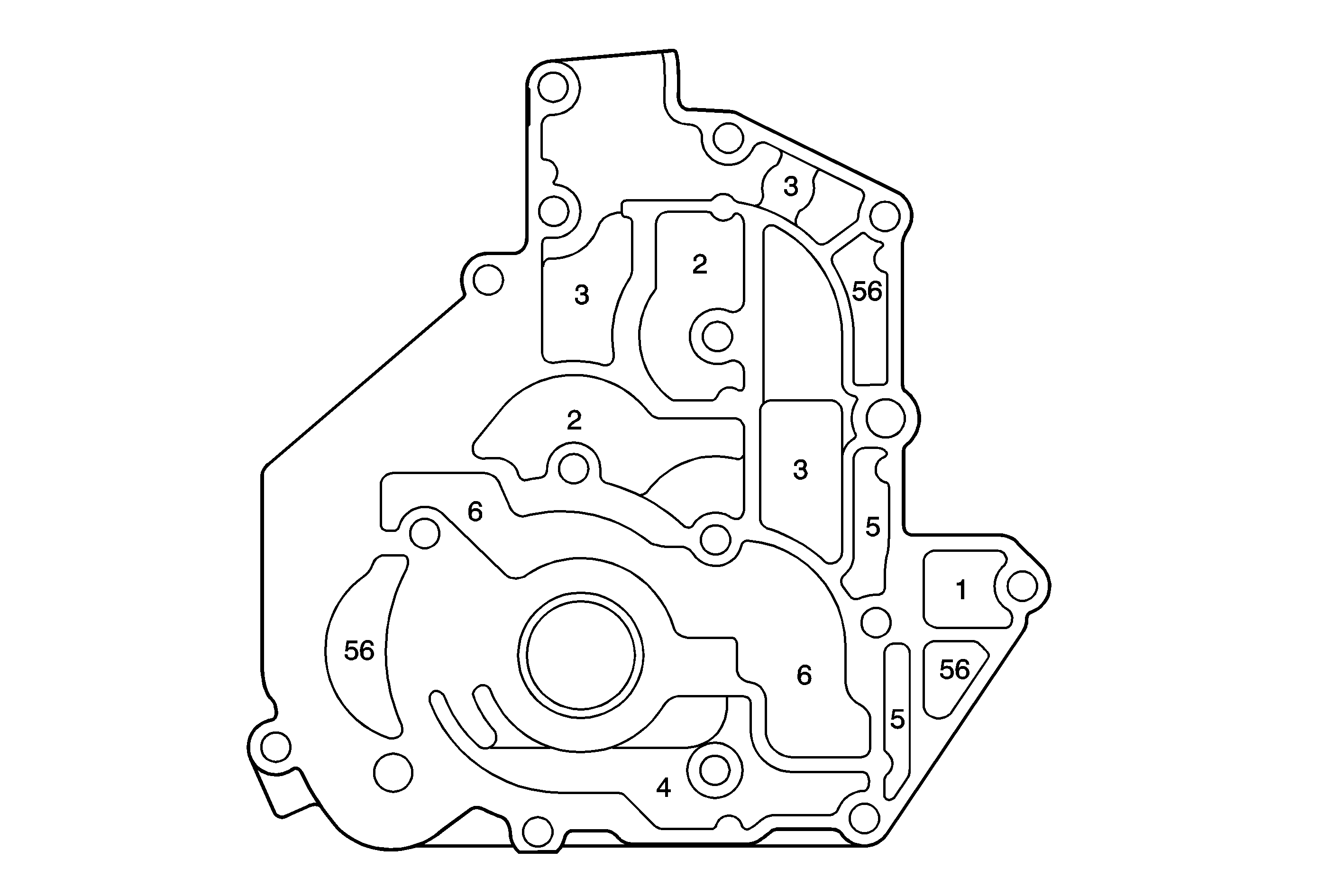
| Figure 18: |
Scavenge Pump Cover Fluid Passages (Primary Pump Body Side)
|
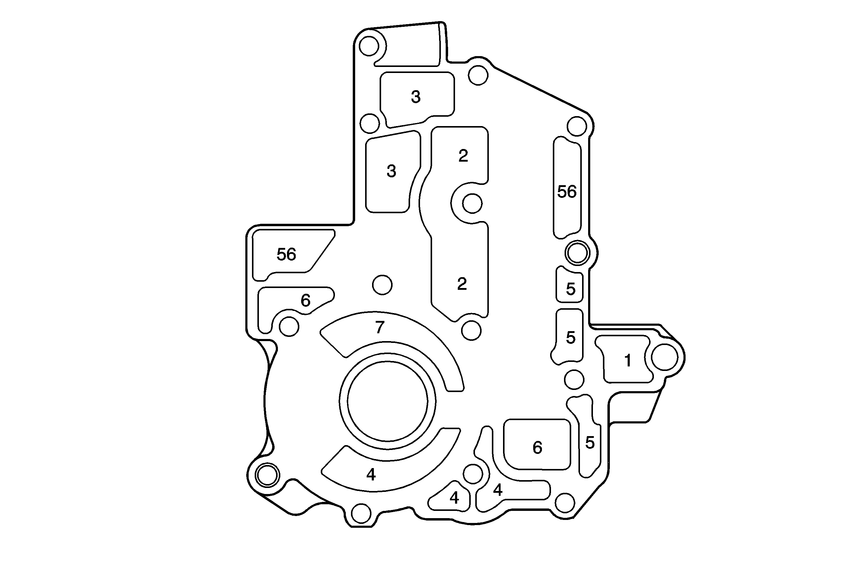
| Figure 19: |
Primary Pump Body Fluid Passages (Secondary Pump Body Side)
|
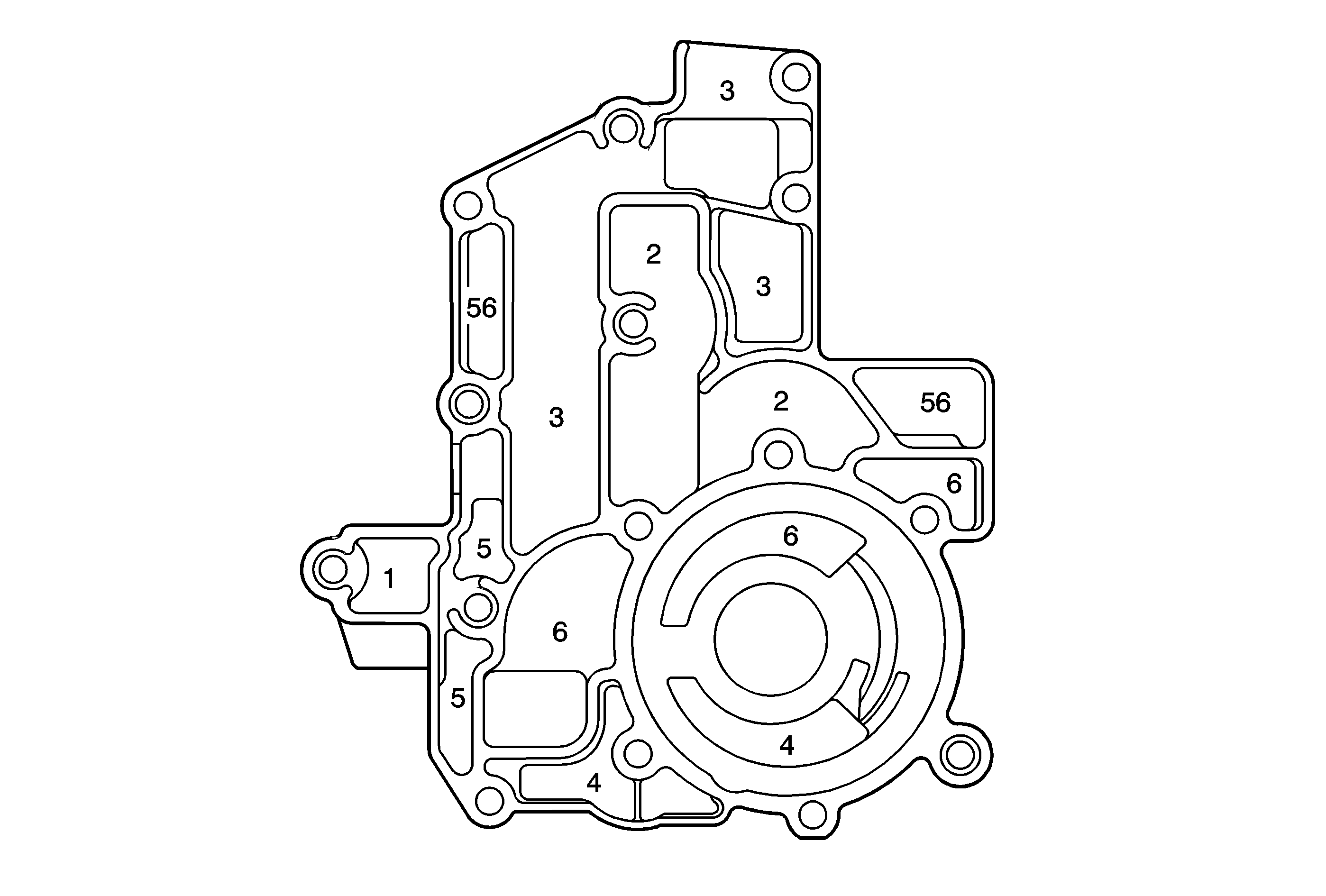
| Figure 20: |
Primary Pump Body Fluid Passages (Scavenge Pump Cover Side)
|
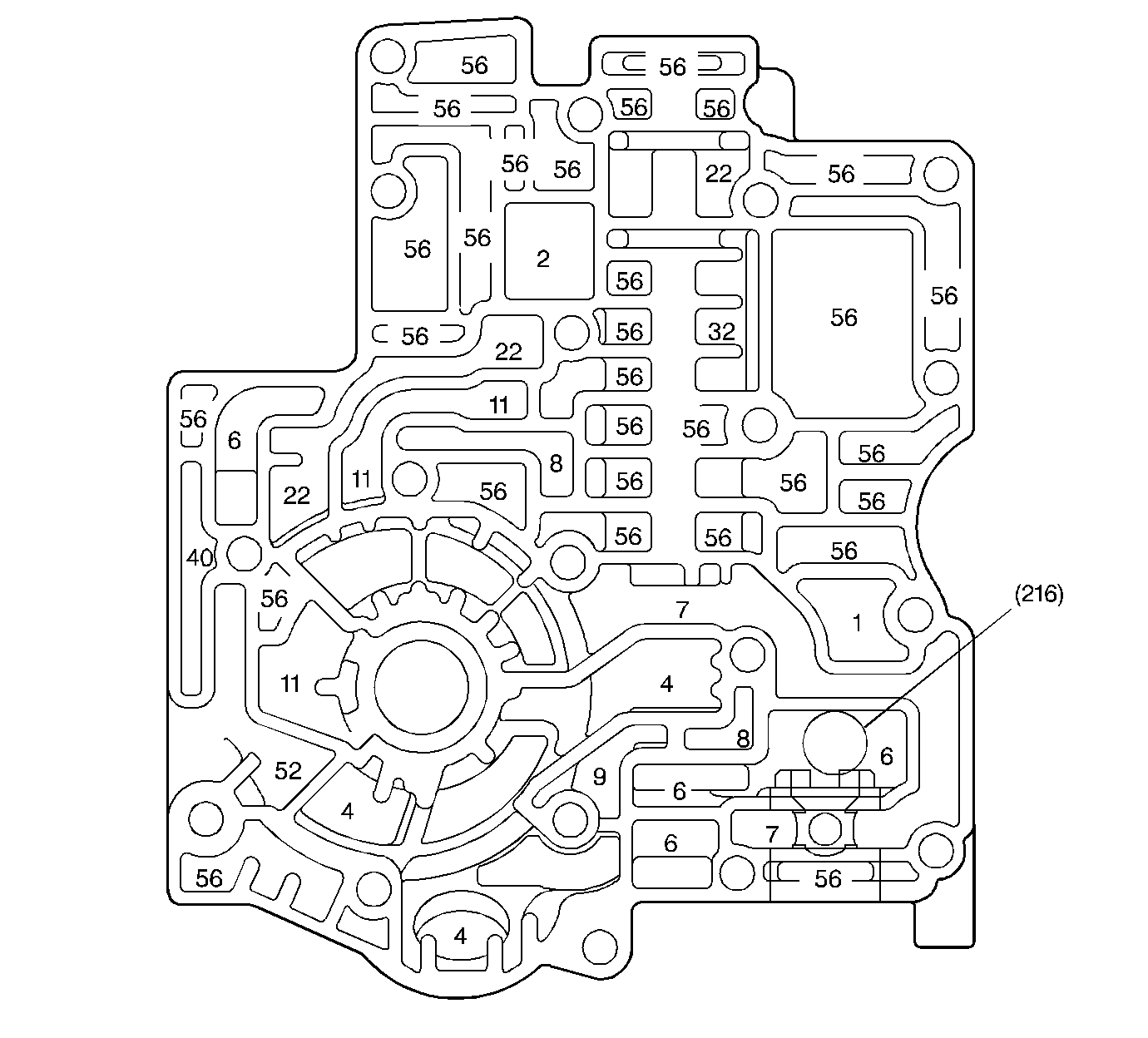
| Figure 21: |
Secondary Pump Body Fluid Passages (Case Cover Side)
|
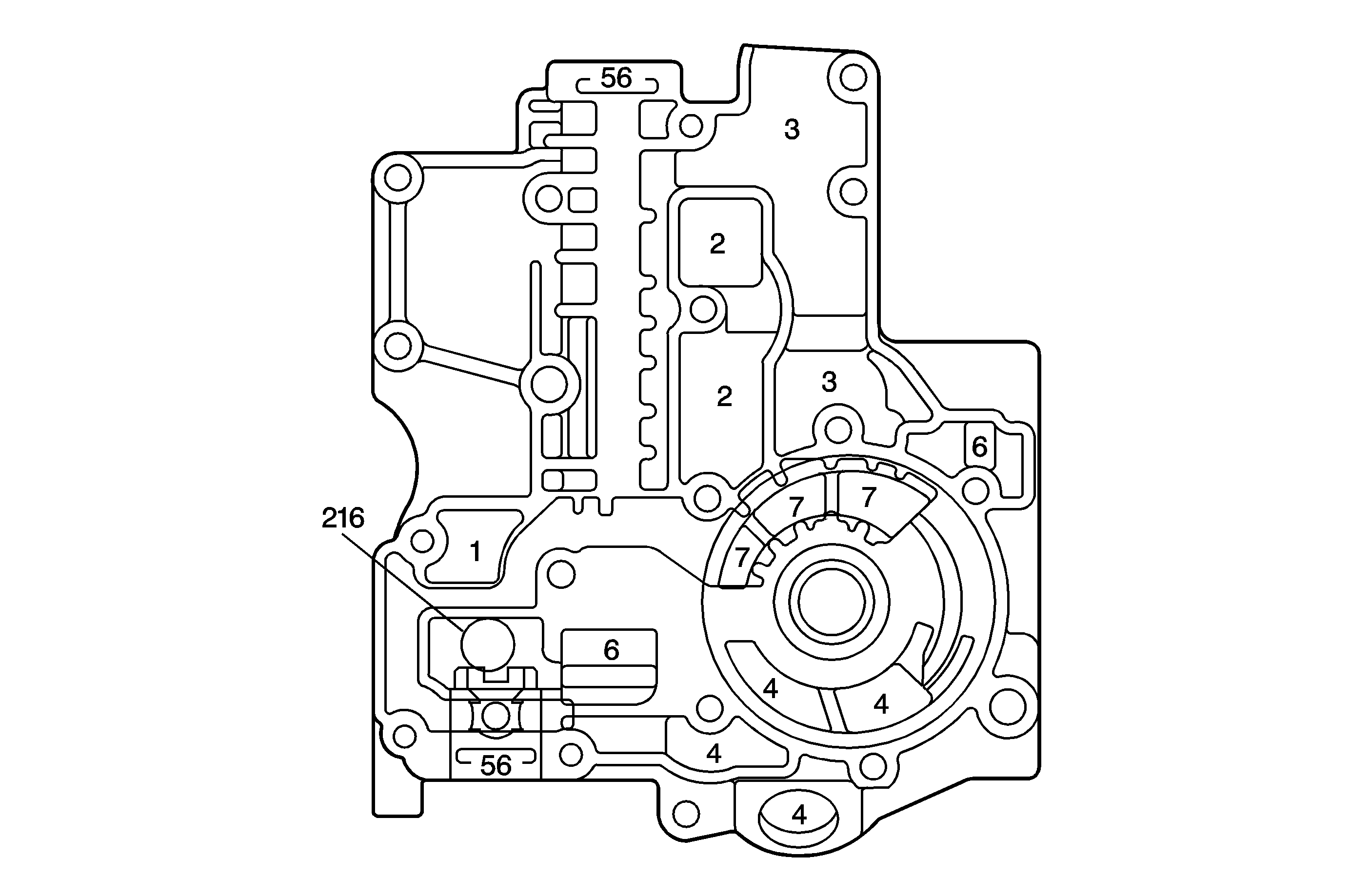
| Figure 22: |
Secondary Pump Body Fluid Passages (Primary Pump Body Side)
|
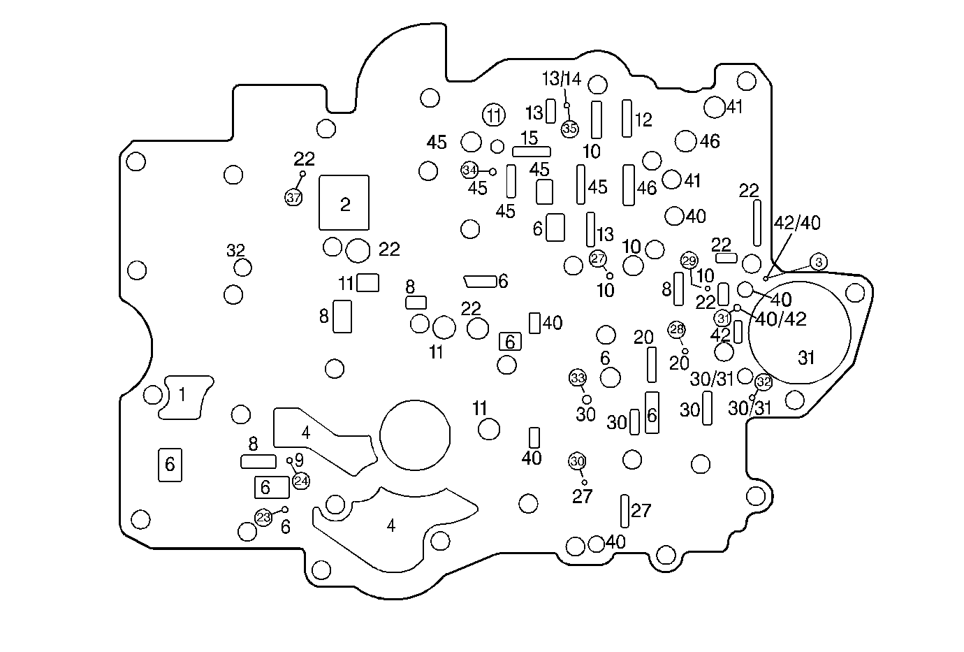
| Figure 23: |
Spacer Plate Fluid Passages (Secondary Pump Body and Upper Control
Valve Body to Case Cover)
|
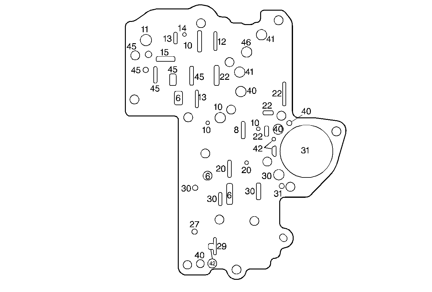
| Figure 24: |
Gasket Fluid Passages (Upper Control Valve Body to Spacer Plate)
|
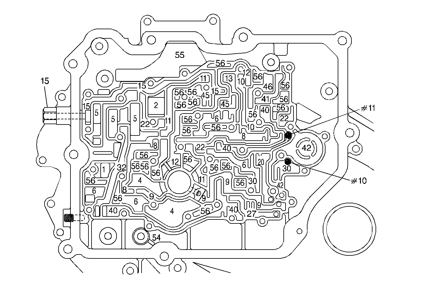
| Figure 25: |
Case Cover Fluid Passages (Secondary Pump Body and Upper Control Valve
Body Side)
|
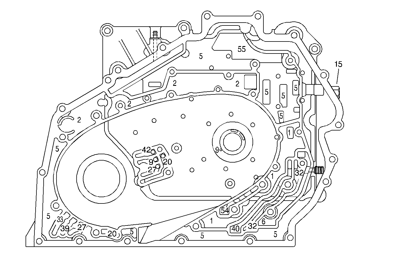
| Figure 26: |
Case Cover Fluid Passages (Case Side)
|
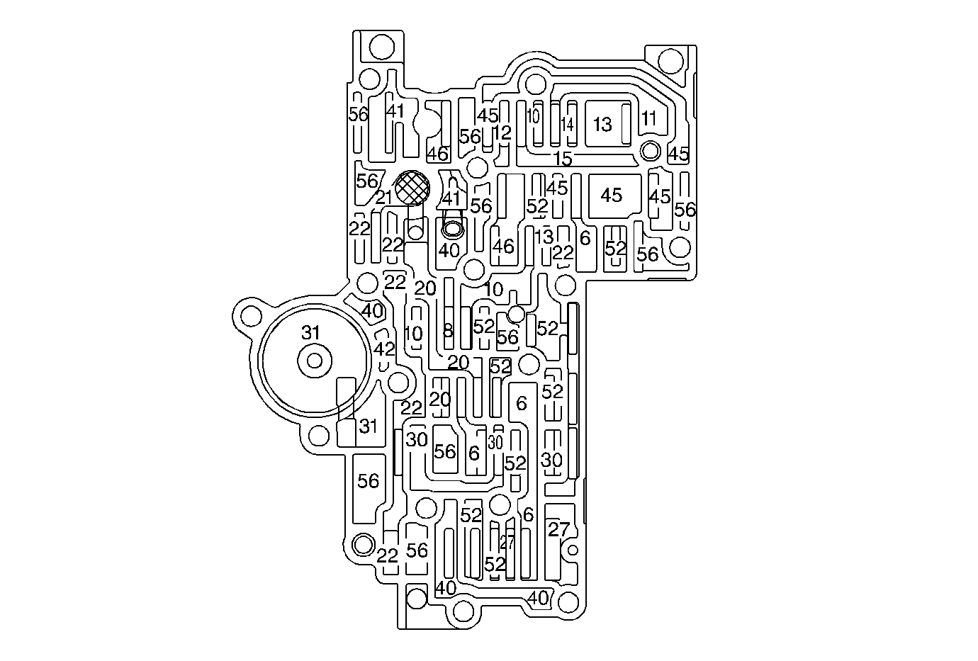
| Figure 27: |
Upper Control Valve Body Fluid Passages (Case Cover Side)
|
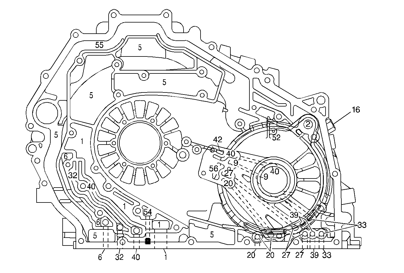
| Figure 28: |
Case and Driven Sprocket Support Fluid Passages (Case Cover Side)
|
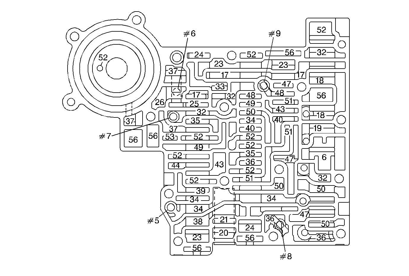
| Figure 29: |
Lower Control Valve Body Fluid Passages (Lower Channel Plate Side)
|
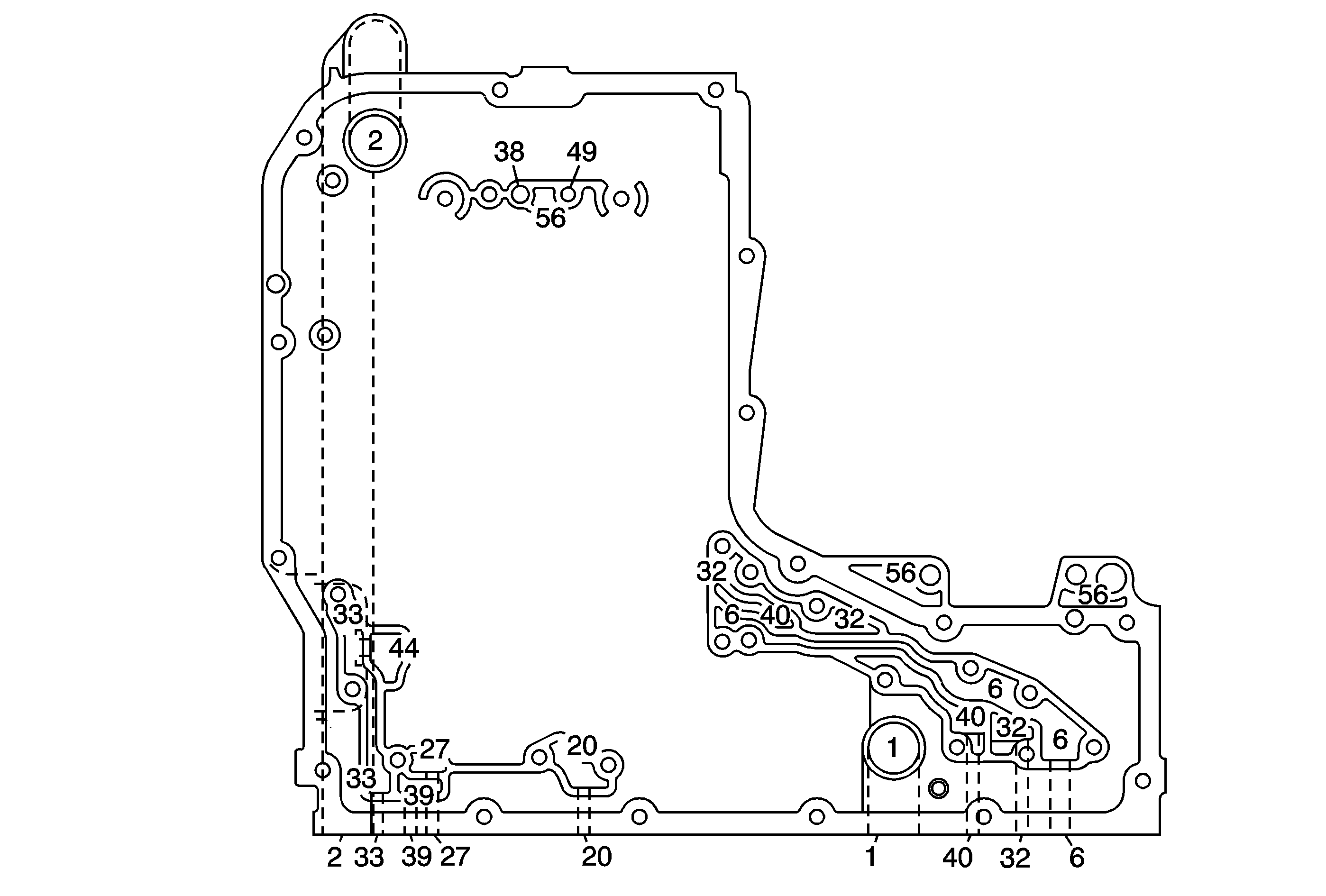
| Figure 30: |
Case Fluid Passages (Lower Channel Plate Side)
|
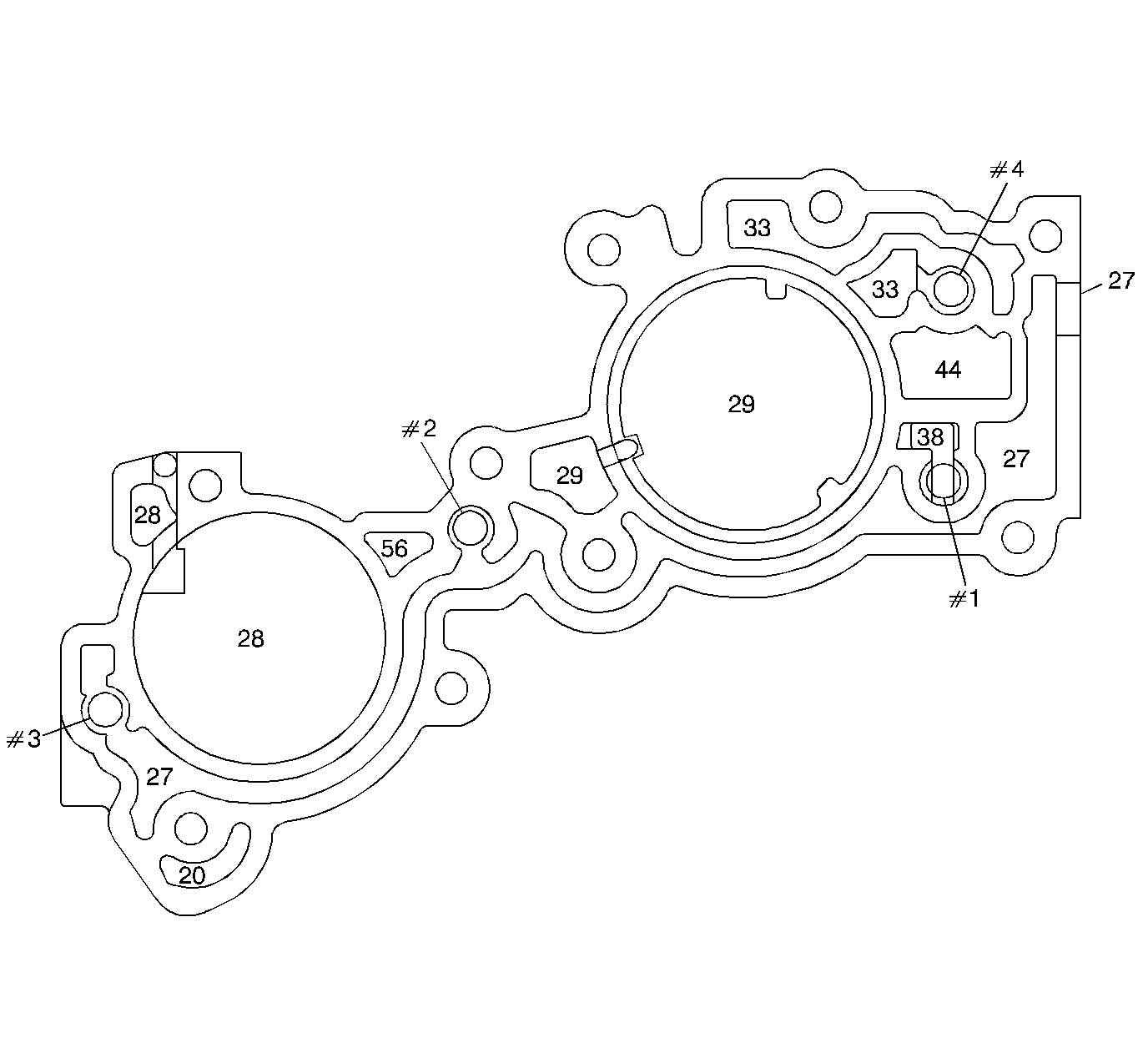
| Figure 31: |
Accumulator Housing Fluid Passages (Lower Channel Plate Side)
|
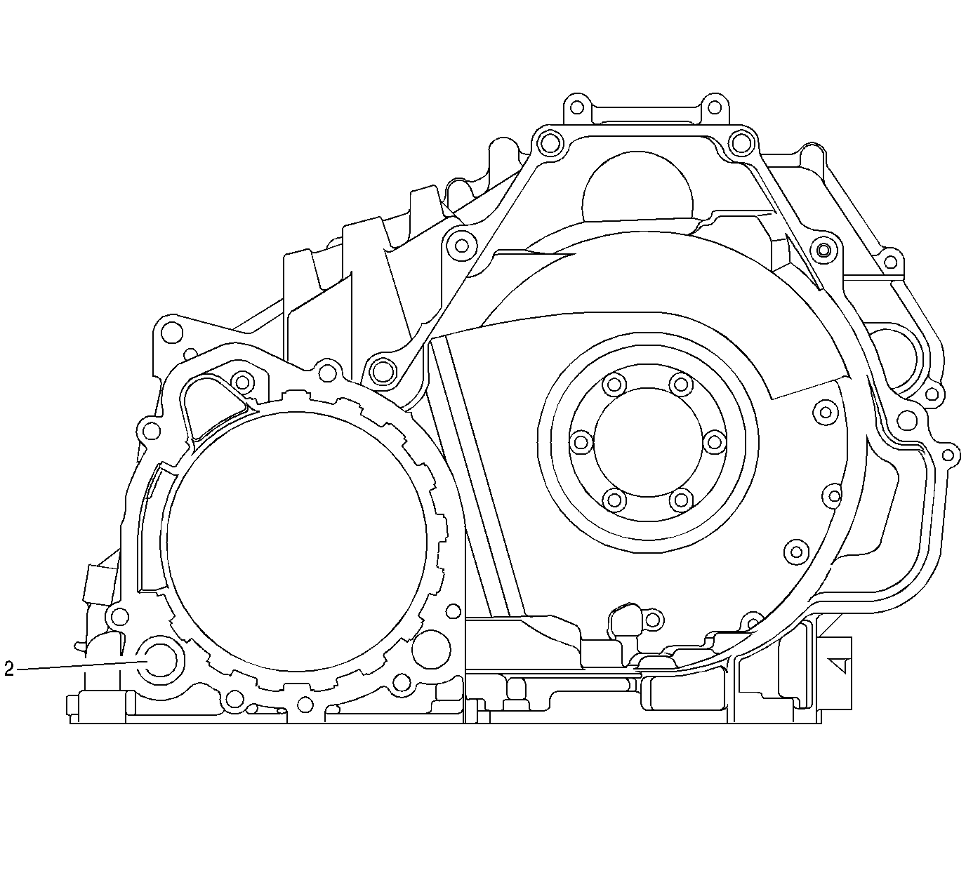
| Figure 32: |
Case Fluid Passages (Case Extension Side)
|
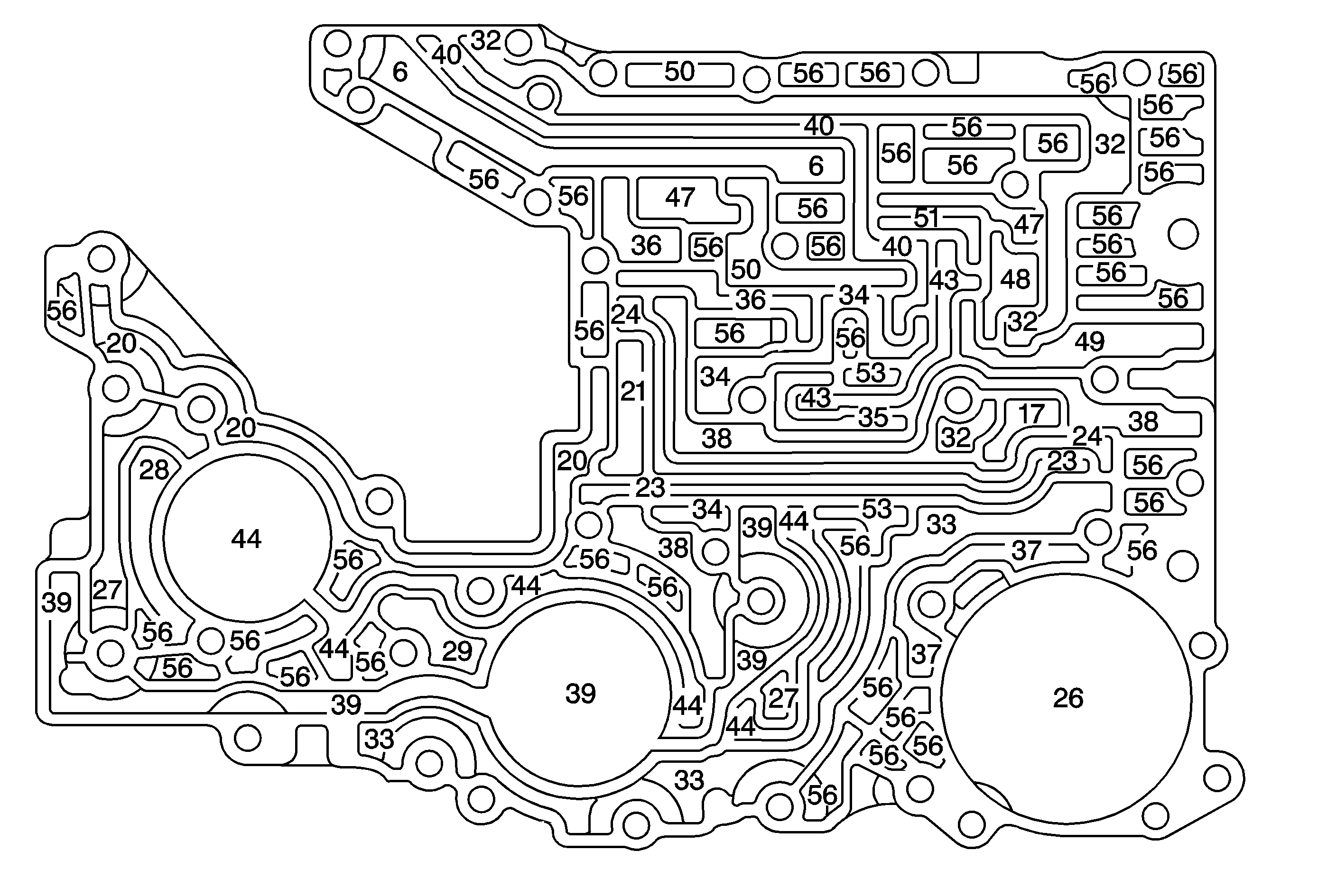
| Figure 33: |
Lower Channel Plate Fluid Passages (Case Bottom Side)
|
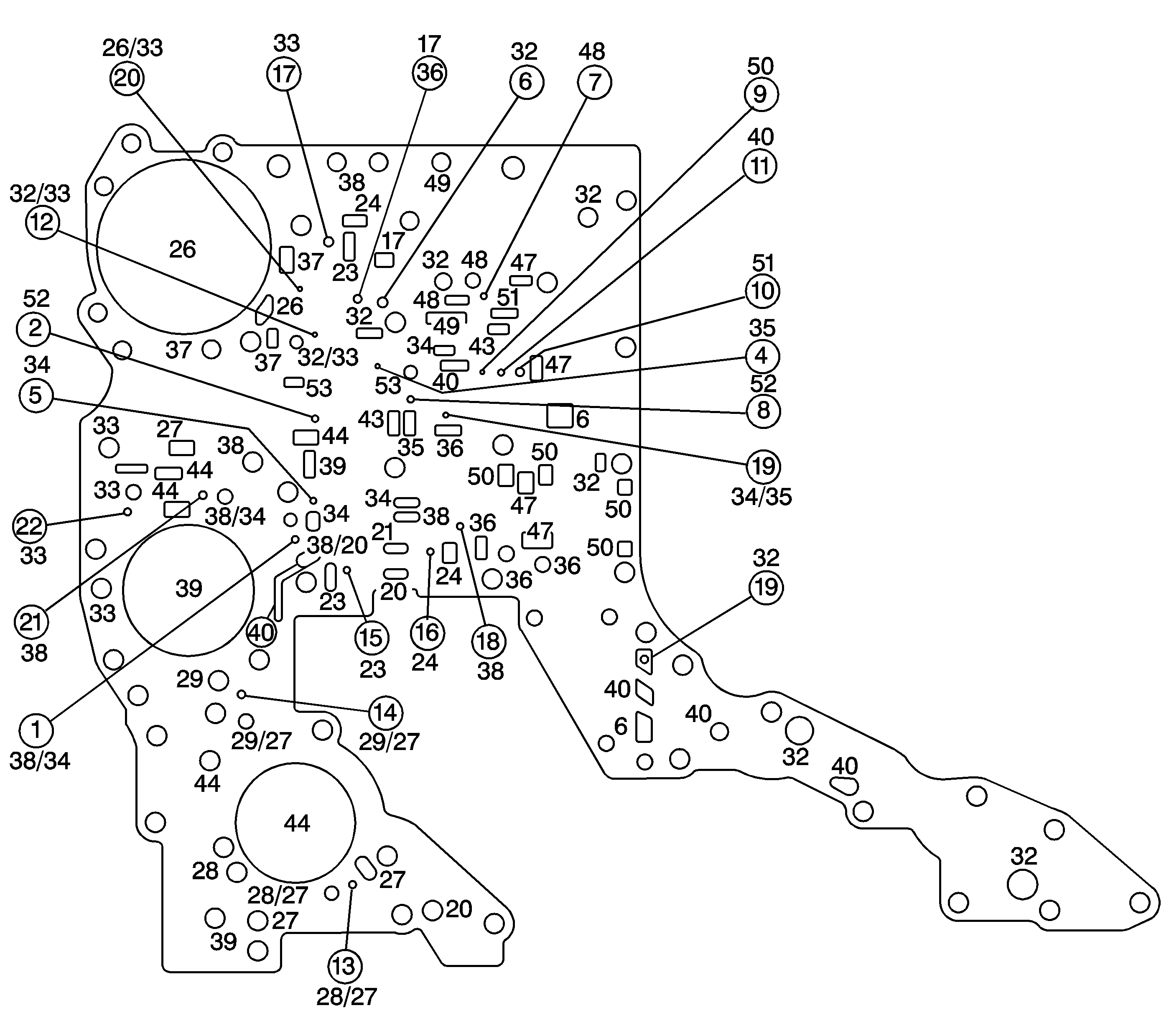
| Figure 34: |
Spacer Plate and Gasket Assembly Fluid Passages (Lower Control Valve
Body to Channel Plate)
|
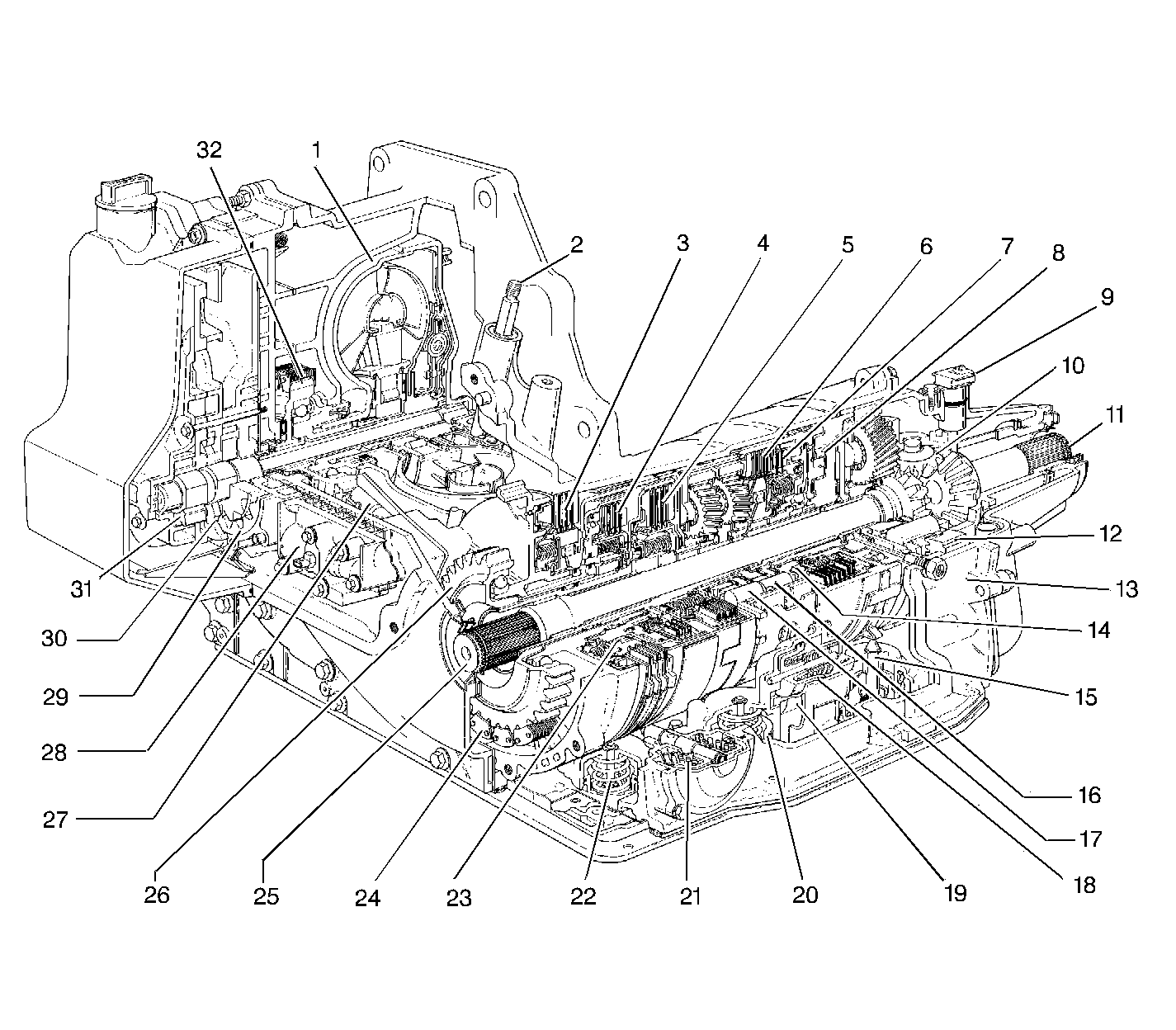
| Figure 35: |
Transaxle Major Components
|