For 1990-2009 cars only
Radiator Surge Tank Outlet Hose/Pipe Replacement LH2
Removal Procedure
- Drain the cooling system. Refer to Cooling System Draining and Filling .
- Remove the fuel injector sight shield. Refer to Fuel Injector Sight Shield Replacement .
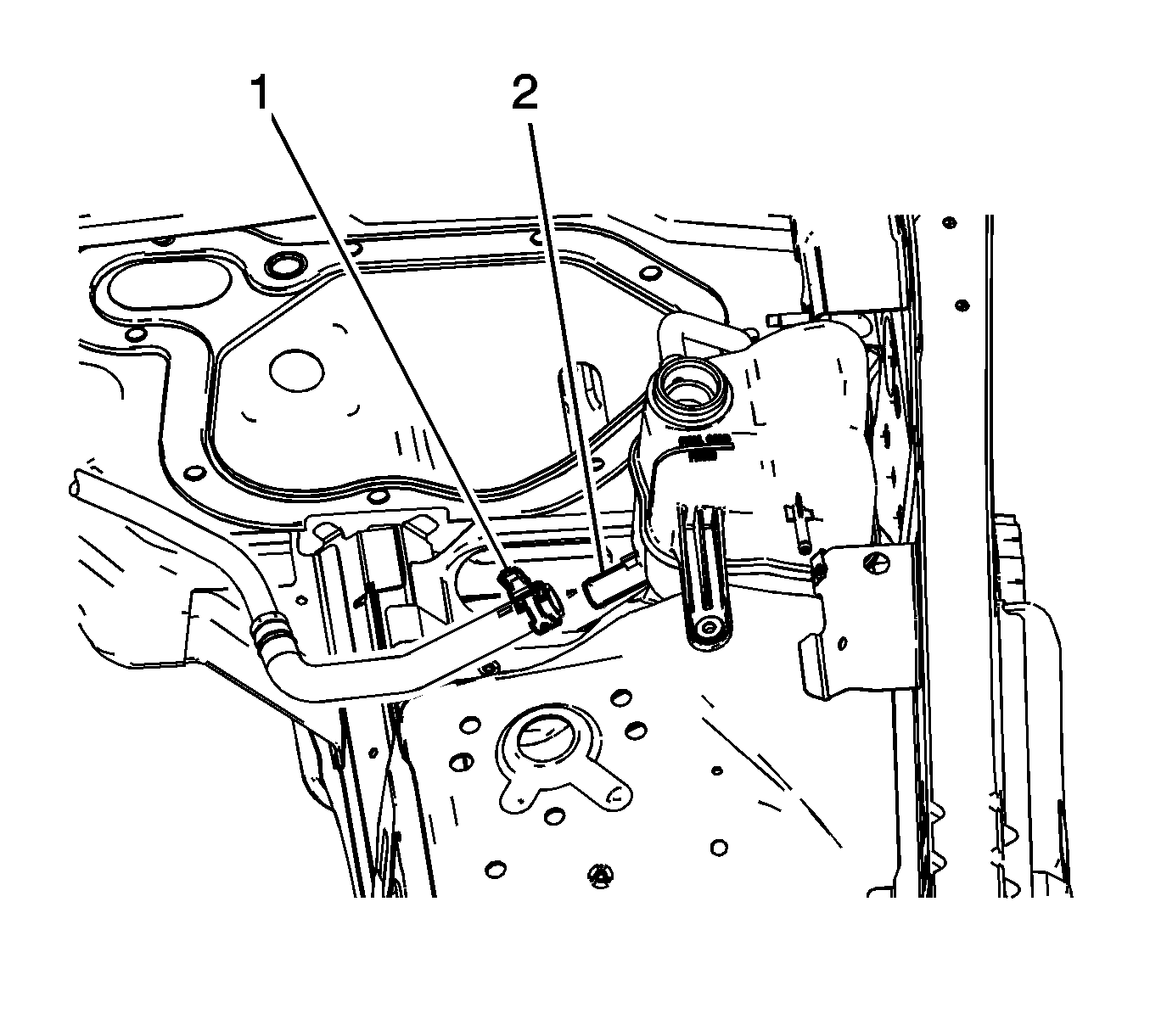
- Compress the clamp (1) and remove the surge tank outlet hose from the surge tank (2).
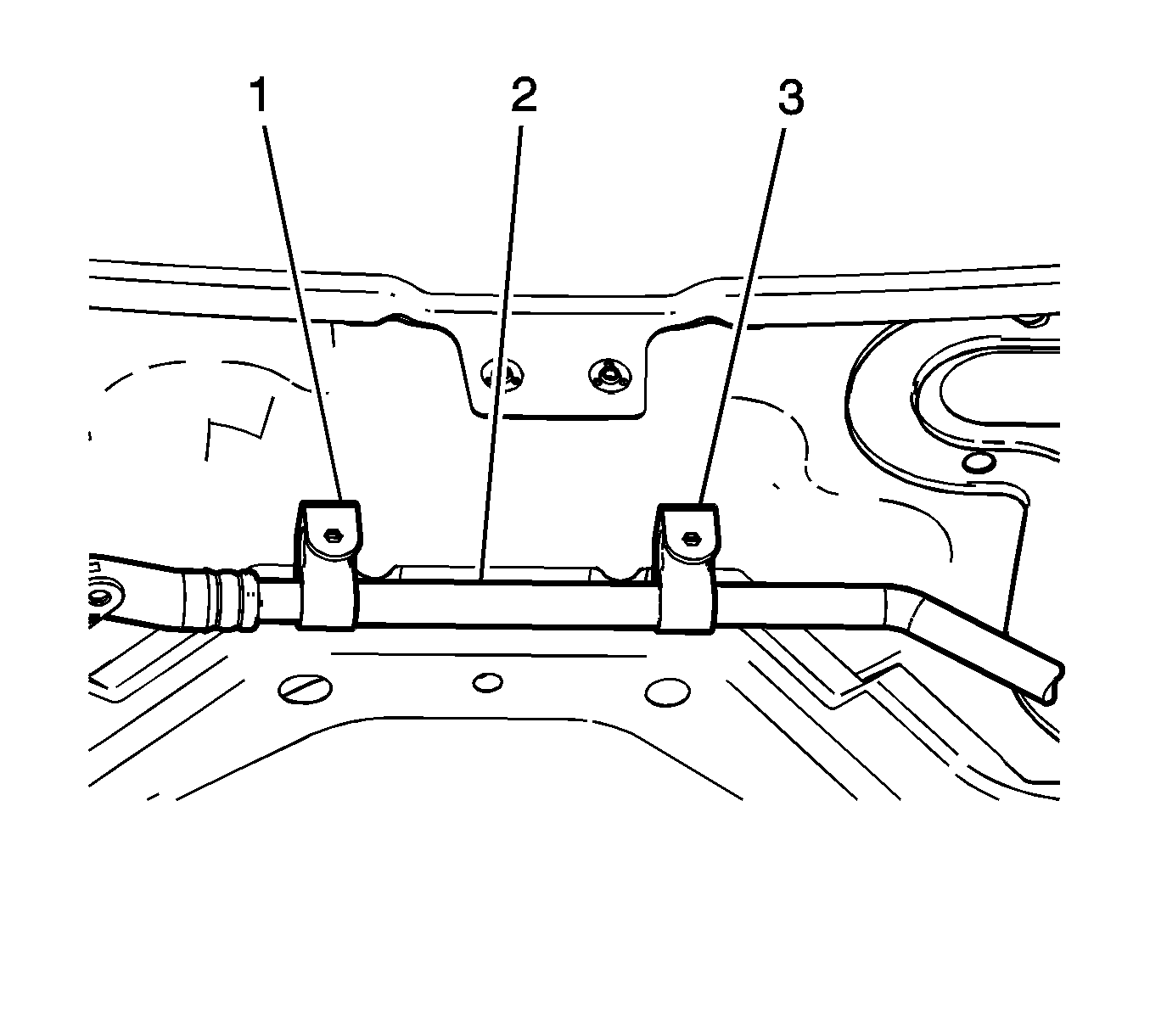
- Separate the hose (2) from the retaining features (1 and 3) on the front of dash.
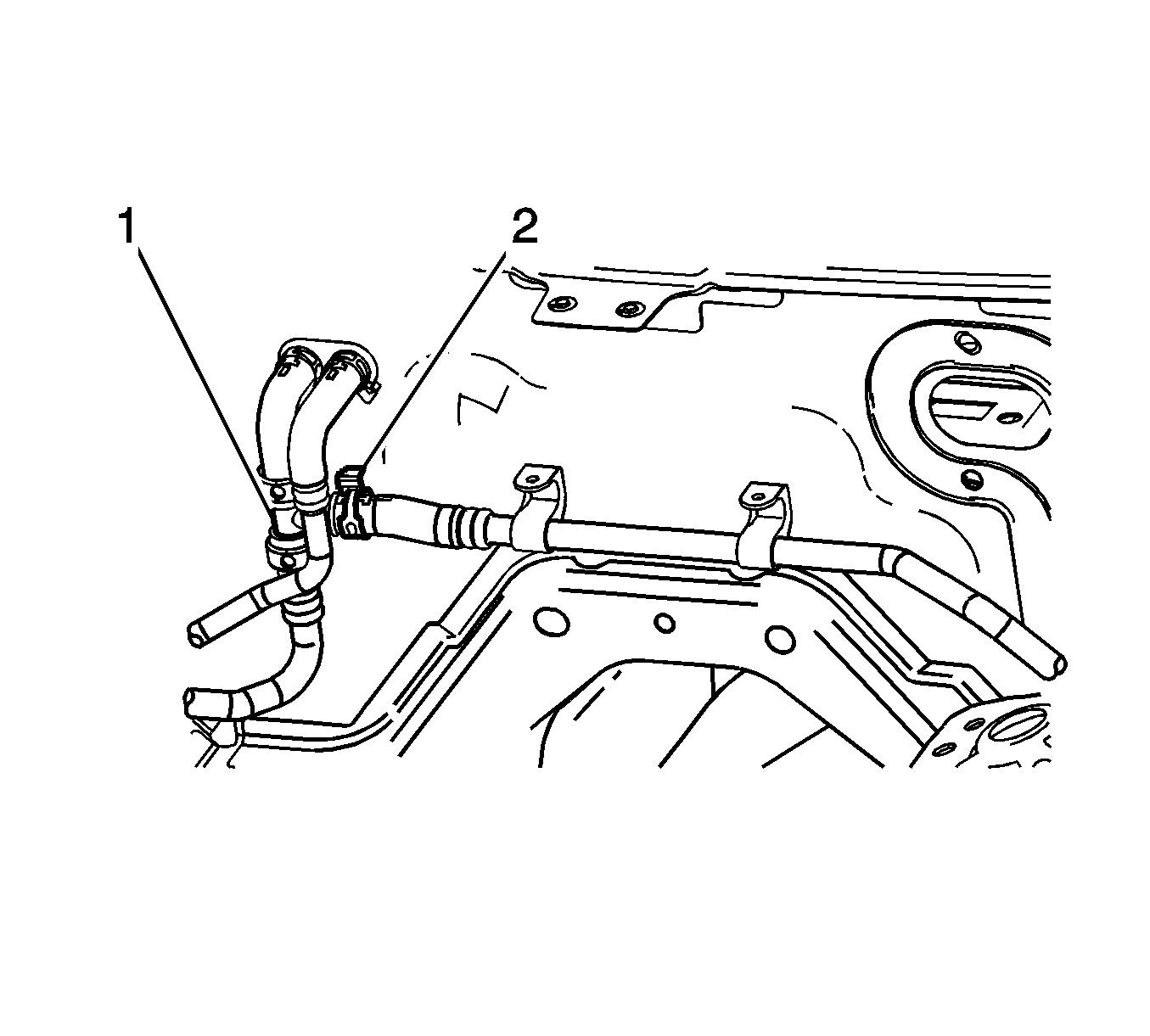
- Compress the clamp (2) and remove the surge tank outlet hose from the heater hose (1).
- Remove the surge tank outlet hose/pipe from the engine compartment.


Installation Procedure
- Position the surge tank outlet hose/pipe to the engine compartment.
- Compress the clamp (2) and connect the surge tank outlet hose to the heater hose (1).
- Install the hose (2) to the retaining features (1 and 3) on the front of dash.
- Compress the clamp (1) and connect the surge tank outlet hose to the surge tank (2).
- Install the fuel injector sight shield. Refer to Fuel Injector Sight Shield Replacement .
- Fill the cooling system. Refer to Cooling System Draining and Filling .


Radiator Surge Tank Outlet Hose/Pipe Replacement Right Hand Drive

Callout | Component Name |
|---|---|
Preliminary Procedure
| |
1 | Surge Tank Outlet Hose Clamp (Qty: 2) |
2 | Surge Tank Outlet Hose |
Radiator Surge Tank Outlet Hose/Pipe Replacement LHD, LY7
Special Tools
J 38185 Hose Clamp Pliers
Removal Procedure
- Drain the cooling system. Refer to Cooling System Draining and Filling.
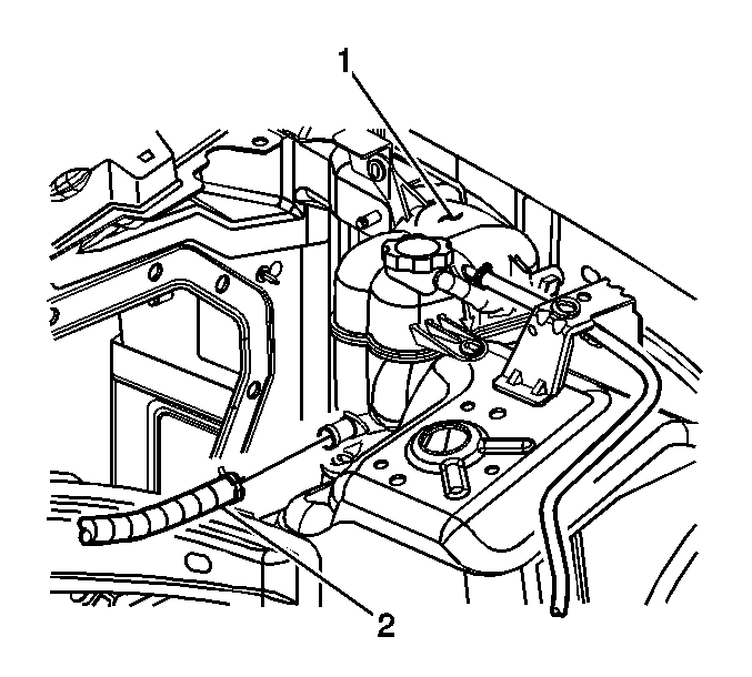
- Position J 38185 to the clamp in order to remove the outlet hose (2) from the surge tank (1).
- Loosen the bolt on the bracket which secures the surge tank outlet hose to the engine.
- Position J 38185 to the clamp in order to remove the surge tank outlet hose from the thermostat assembly.
- Remove the surge tank outlet hose/pipe from the engine.

Installation Procedure
- Position the surge tank outlet hose/pipe to the engine.
- Position J 38185 to the clamp in order to connect the surge tank outlet hose to the thermostat assembly.
- Install the bolt to the bracket securing the surge tank outlet pipe to the engine.
- Position J 38185 to the clamp in order to connect the outlet hose (2) to the surge tank (1).
- Fill the cooling system. Refer to Cooling System Draining and Filling.
Caution: Refer to Fastener Caution in the Preface section.
Tighten
Tighten the bolt to 9 N·m (80 lb in).

