Product Safety - Brake Pipe Contact-Replace Section of Brake Pipe (Right-Hand Drive Vehicles)

| Subject: | 07119 -- Brake Pipe Contact - Replace Section of Brake Pipe |
| Models: | 2007 Cadillac SRX |
| Right-Hand Drive |
Condition
General Motors has decided that a defect, which relates to motor vehicle safety, exists in certain 2007 Cadillac SRX right-hand drive vehicles. Some of these vehicles have a clearance condition in which one or both rear brakes pipe may contact the intermediate steering shaft. If either pipe contacts the intermediate steering shaft, a hole could be worn in the brake pipe and brake fluid would leak out. The driver may notice the brake pedal going closer to the floor. If enough brake fluid has leaked from the brake system, the brake system warning light will illuminate in the instrument panel and braking would be limited to two wheels. If this were to occur, greater brake pedal force and a longer distance will be required to stop the vehicle. If the driver ignores these warnings and continues to operate the vehicle, a hole could be worn in the second brake pipe. Once sufficient brake fluid leaked out of the second pipe, the service brakes would not work and a vehicle crash could occur.
Correction
Dealers are to replace a section of brake pipe with one that has been redesigned to allow sufficient clearance between the brake pipe and intermediate steering shaft.
Vehicles Involved
Involved are certain 2007 Cadillac SRX right-hand drive vehicles built within these VIN breakpoints:
Year | Division | Model | From | Through |
|---|---|---|---|---|
2007 | Cadillac | SRX | 70123704 | 70181470 |
Important: Dealers are to confirm vehicle eligibility prior to beginning repairs by using GMVIS. Not all vehicles within the above breakpoints may be involved.
For dealers with involved vehicles, a listing with involved vehicles containing the complete vehicle identification number, customer name, and address information has been prepared and will be sent directly to dealers. Dealers will not have a report available if they have no involved vehicles currently assigned.
The listing may contain customer names and addresses obtained from Motor Vehicle Registration Records. The use of such motor vehicle registration data for any purpose other than follow-up necessary to complete this recall is a violation of law in several countries. Accordingly, you are urged to limit the use of this report to the follow-up necessary to complete this recall.
Parts Information
Part kits required to complete this recall are being shipped to dealers/ports at no charge . Do not order kits from General Motors Service and Parts Operations (GMSPO).
Special Tool
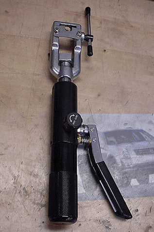
Beginning the week of April 23, 2007, each region will be shipped a supply of ISO Metric Bubble Flaring and 45 Degree Inverted Flaring Kit, J 45405, for use in this recall. Before beginning a vehicle repair, contact the regional headquarters to obtain the tool on a loan basis.
Service Procedure
Tools Required
J 45405 ISO Metric Bubble Flaring and 45 Degree Inverted Flaring Kit (contact your regional headquarters to obtain a tool on loan)
- Raise and support the vehicle. Refer to Lifting and Jacking the Vehicle in SI.
- Remove the right front tire and wheel. Refer to Tire and Wheel Removal and Installation in SI.
- Remove the right-hand side wheelhouse panel. Refer to Wheelhouse Panel Replacement in SI.
- Remove the front air deflector. Refer to Front Air Deflector Replacement in SI.
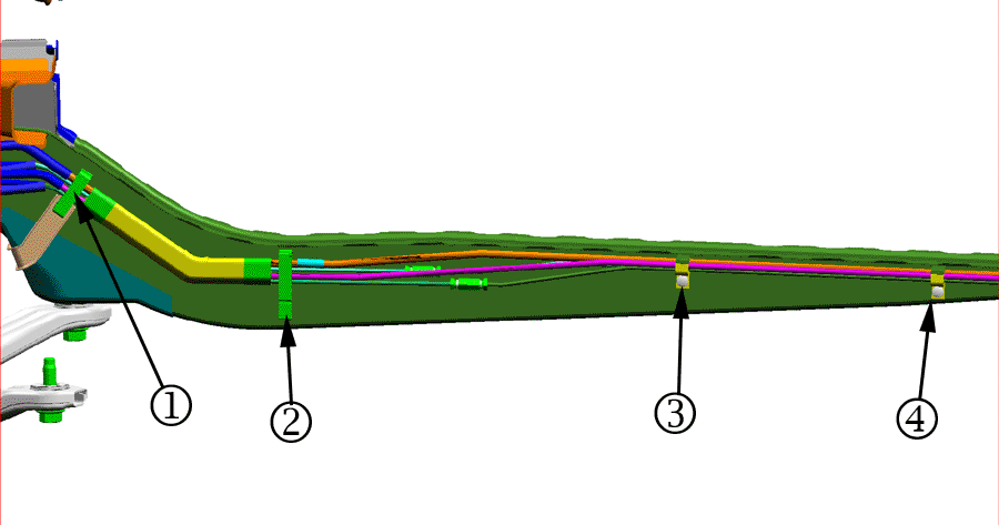
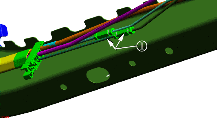
- Remove the four fuel and brake line bundle clips along the right frame rail. The first fuel and brake line bundle clip (1) is located to the rear of the cradle near the catalytic converter. The last fuel and brake line bundle clip (4) is located near the exhaust insulator, hanger and bracket location. Refer to the illustration.
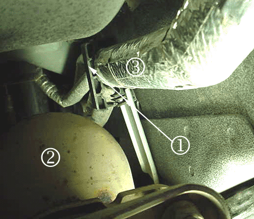
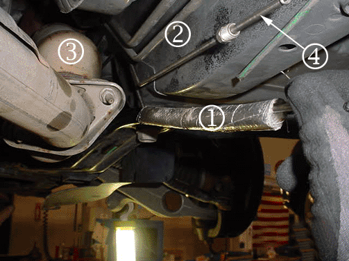
- Remove the fuel and brake line bundle clip and bracket (1) located forward of the cradle and underneath the rear portion of the wheelhouse panel. The fuel and brake line bundle is between the catalytic converter (2) and protective heat wrap (3).
- Cut the two brake lines. The brake lines should be cut within 25 mm (1 in) rearward of second fuel and brake line bundle clip. Mark the left and right rear brake lines with a marker or tape.
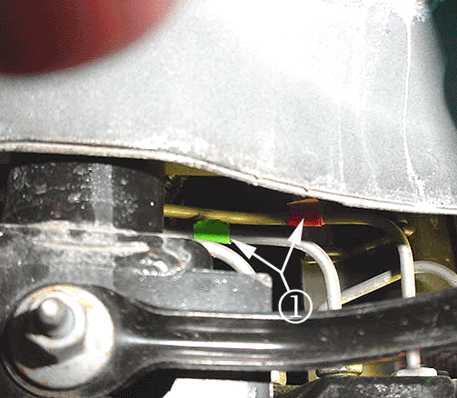
- The right rear brake line is wrapped with red tape (1). Before removing the brake line, mark the port and nut location with a red marker. The left rear brake line is wrapped with green tape.
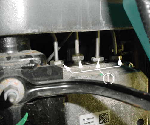
- Remove the brake tube nuts (1) from the ABS module.
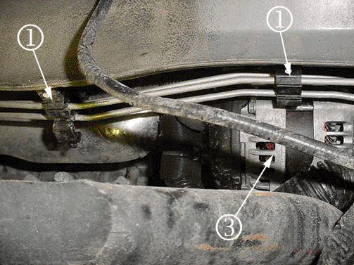
- Remove the brake line bundle clips (1) near the alternator (3).
- Remove the two brake lines from the vehicle. Pull the brake lines away from the ABS module along the frame rail.
- Route the right rear brake line (line wrapped with red tape) along the frame rail to the ABS module.
- Connect right rear brake line to the ABS module. Tighten the nuts (1).
- Route the left rear brake line (line is wrapped with green tape) along the frame rail to the ABS module.
- Connect the right rear brake line to the ABS module. Tighten the nuts (1).
- Install the two brake line bundle clips (1) located near the alternator (3).
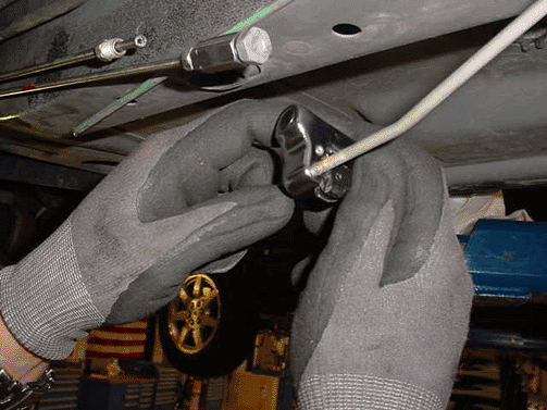
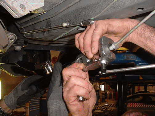
- Flare the existing brake lines using J-45405, ISO Metric Bubble Flaring and 45 Degree Inverted Flaring Kit. Use 3/16-inch detail included with J 45405 tool.
- Attach protective heat wrap (1) around the brake lines. Push the protective heat wrap (1) up and forward to the catalytic converter (3) and cradle location.
- Connect the new brake lines with the existing brake lines with a union (1). The union for these brake lines is between the second and third fuel and brake line bundle clip. Adjust the cut of the existing brake line to the union location.
- Install the fuel and brake line bundle clip (1) and bracket (2) forward of the cradle and underneath the rear portion of the wheelhouse panel.
- Install the three fuel and brake line bundle clips (locations 2, 3 and 4). Refer to the illustration.
- Install the right-hand side wheelhouse panel. Refer to Wheelhouse Panel Replacement in SI.
- Install the front air deflector. Refer to Front Air Deflector Replacement in SI.
- Install the right front tire and wheel. Refer to Tire and Wheel Removal and Installation in SI.
- Lower the vehicle.
- Bleed the brake system. Refer to Hydraulic Brake System Bleeding in SI.
Notice: Do not push the brake lines forward toward the ABS module to avoid damaging the steering assembly.
Important: Use two technicians to perform steps 11-14. One technician will guide the brake line rearward of the catalytic converter. The second technician will route the brake lines from the ABS module location.

Tighten
Tighten the nuts (1) to 20 N·m (15 lb ft).

Tighten
Tighten the nuts (1) to 20 N·m(15 lb ft).
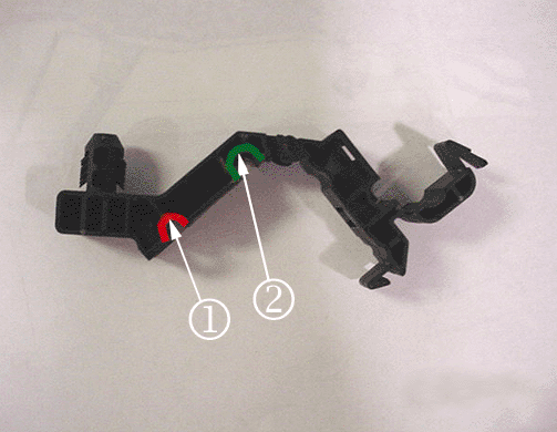
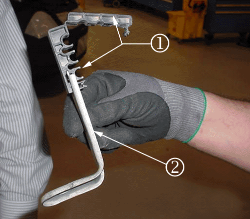
Important: The right rear brake line must be inserted into the red (1) area of the brake bundle clip. The left rear brake line must be inserted into the green (2) area of the brake bundle clip.


Claim Information
Submit a Product Recall Claim with the information indicated below:
Repair Performed | Part Count | Part No. | Parts Allow | CC-FC | Labor Op | Labor Hours | Net Item |
|---|---|---|---|---|---|---|---|
Install New Section of Brake Pipes | N/A | N/A | N/A | MA-96 | V1605 | 2.5 | * |
* The amount identified in the "Net Item" column should represent the actual sum total of the current GMSPO Dealer net price plus applicable Landed Cost Mark-Up for the brake fluid needed to perform the required repairs, not to exceed $24.47 USD. | |||||||
Refer to the General Motors WINS Claims Processing Manual for details on Product Recall Claim Submission.
Customer Notification
Letters will be sent to known owners of record located within areas covered by the US National Traffic and Motor Vehicle Safety Act. For owners outside these areas, dealers should notify customers using the attached sample letter.
Dealer Recall Responsibility
All unsold new vehicles in dealers' possession and subject to this recall must be held and inspected/repaired per the service procedure of this recall bulletin before customers take possession of these vehicles.
Dealers are to service all vehicles subject to this recall at no charge to customers, regardless of mileage, age of vehicle, or ownership, from this time forward.
Customers who have recently purchased vehicles sold from your vehicle inventory, and for which there is no customer information indicated on the dealer listing, are to be contacted by the dealer. Arrangements are to be made to make the required correction according to the instructions contained in this bulletin. A copy of the customer letter is provided in this bulletin for your use in contacting customers. Recall follow-up cards should not be used for this purpose, since the customer may not as yet have received the notification letter.
In summary, whenever a vehicle subject to this recall enters your vehicle inventory, or is in your dealership for service in the future, you must take the steps necessary to be sure the recall correction has been made before selling or releasing the vehicle.
May 2007Dear General Motors Customer:
General Motors has decided that a defect that relates to motor vehicle safety exists in certain 2007 model year Cadillac SRX right-hand drive vehicles. As a result, GM is conducting a safety recall. We apologize for this inconvenience. However, we are concerned about your safety and continued satisfaction with our products.
I M P O R T A N T | |||||||
|---|---|---|---|---|---|---|---|
| |||||||
Why is your vehicle being recalled?
Your vehicle may have a clearance condition in which one or both rear brakes pipe may contact the intermediate steering shaft. If either pipe contacts the intermediate steering shaft, a hole could be worn in the brake pipe and brake fluid would leak out. The driver may notice the brake pedal going closer to the floor. If enough brake fluid has leaked from the brake system, the brake system warning light will illuminate in the instrument panel and braking would be limited to two wheels. If this were to occur, greater brake pedal force and a longer distance will be required to stop the vehicle. If the driver ignores these warnings and continues to operate the vehicle, a hole could be worn in the second brake pipe. Once sufficient brake fluid leaked out of the second pipe, the service brakes would not work and a vehicle crash could occur.
What will we do?
Your GM dealer will replace a section of brake pipe with one that has been redesigned to allow sufficient clearance between the brake pipe and intermediate steering shaft. This service will be performed for you at no charge . It is likely that your dealer will need your vehicle longer than the actual service correction time of approximately 2 hours and 30 minutes because of service scheduling requirements.
If your vehicle is within the New Vehicle Limited Warranty your dealer may provide you with shuttle service or some other form of courtesy transportation while your vehicle is at the dealership for this repair. Please refer to your Owner’s Manual and your dealer for details on courtesy transportation.
Scott Lawson
General Director,
Customer and Relationship Services
07119
