GM Service Manual Online
For 1990-2009 cars only
Makes
🢒
Cadillac
🢒
2007
🢒
SRX
🢒
Power and Signal Distribution
🢒
Wiring Systems and Power Management
🢒 Antilock Brake System Schematics
Figure
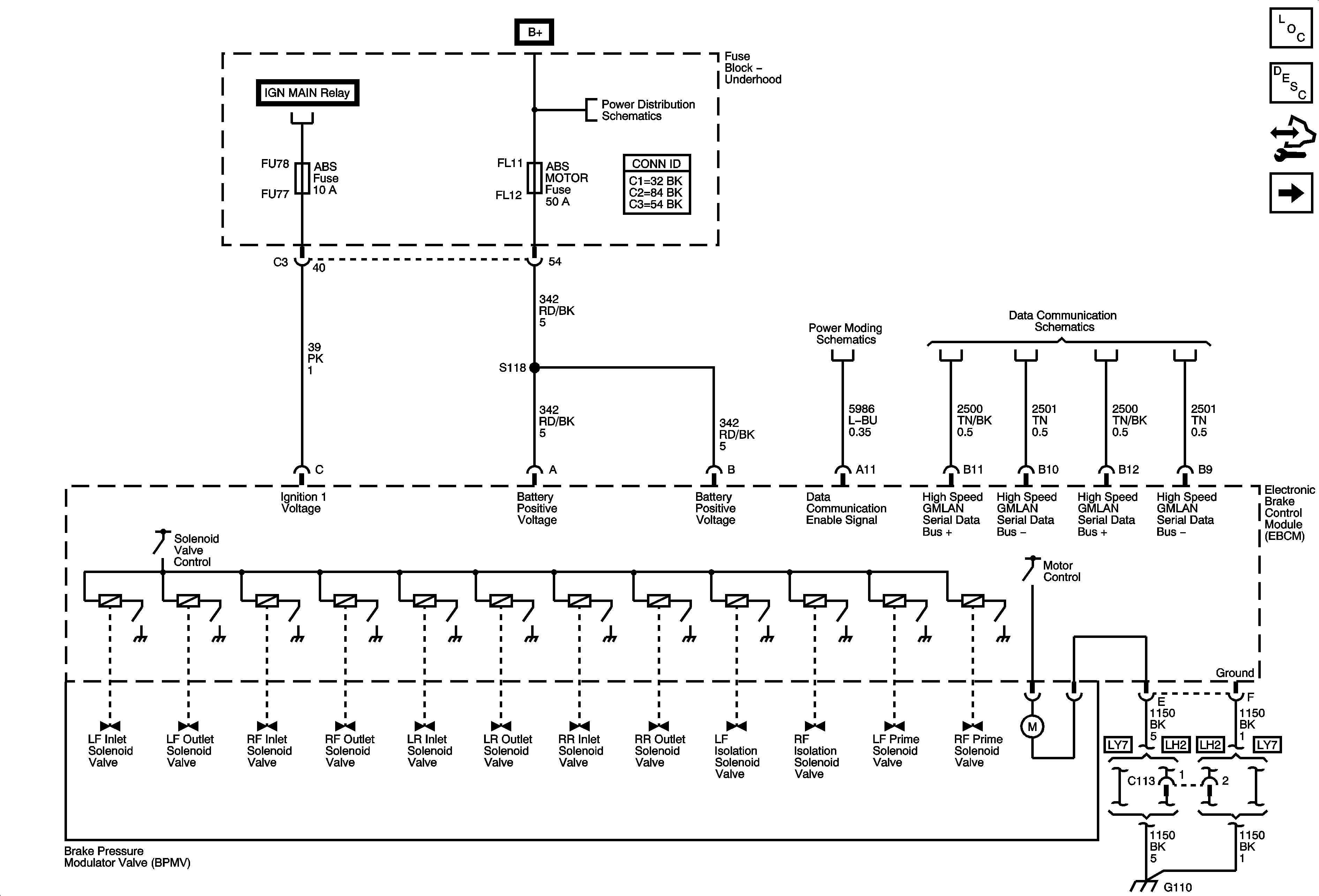
1:
Power, Ground and Serial Data
Master Electrical Component List
ABS Description and Operation
Control Module References
Wheel Speed Sensors
Ignition Power Modes - RUN
Underhood Fuse Block B+ Bus - 1 of 2
Power Modes - ACCY and RAP
High Speed GMLAN
G102, G105, G107, G108, G109, G110
Figure
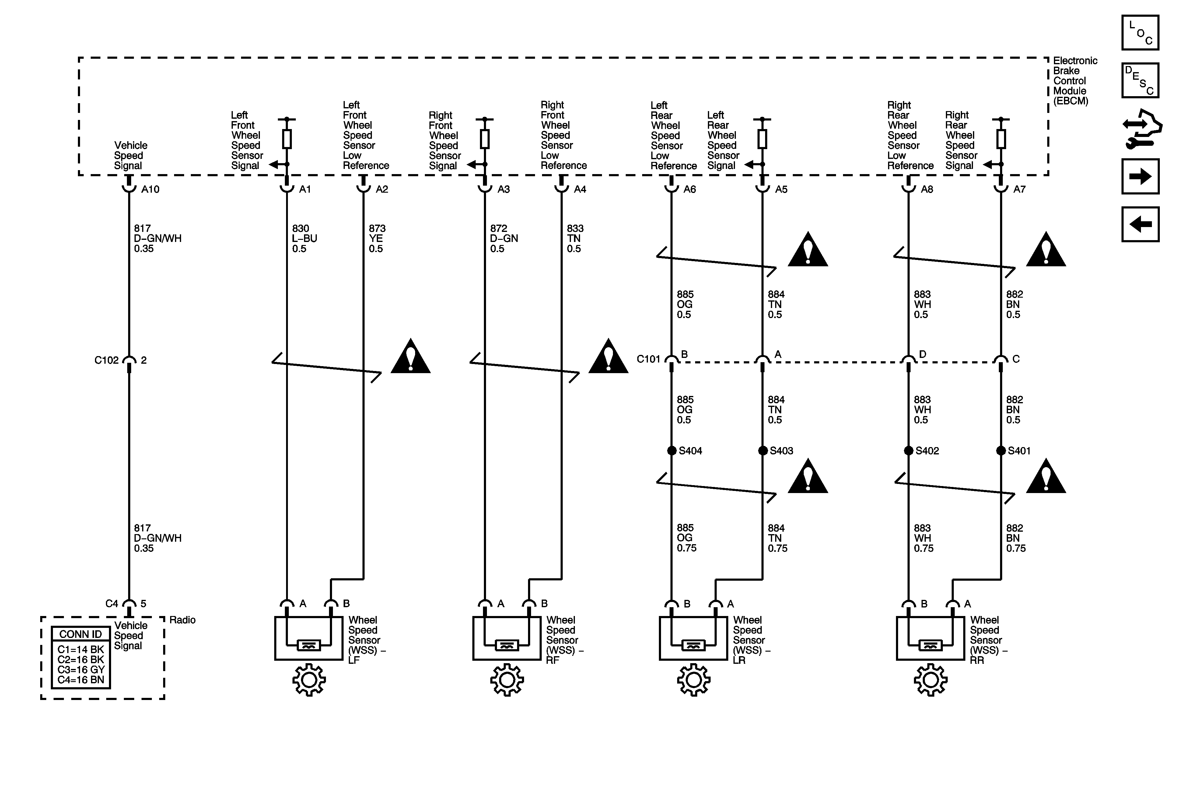
2:
Wheel Speed Sensors
Master Electrical Component List
ABS Description and Operation
Control Module References
Indicator, Traction Control, and Brake Pedal Position Sensor
Power, Ground and Serial Data
Antilock Brake System Schematic Icons
Figure
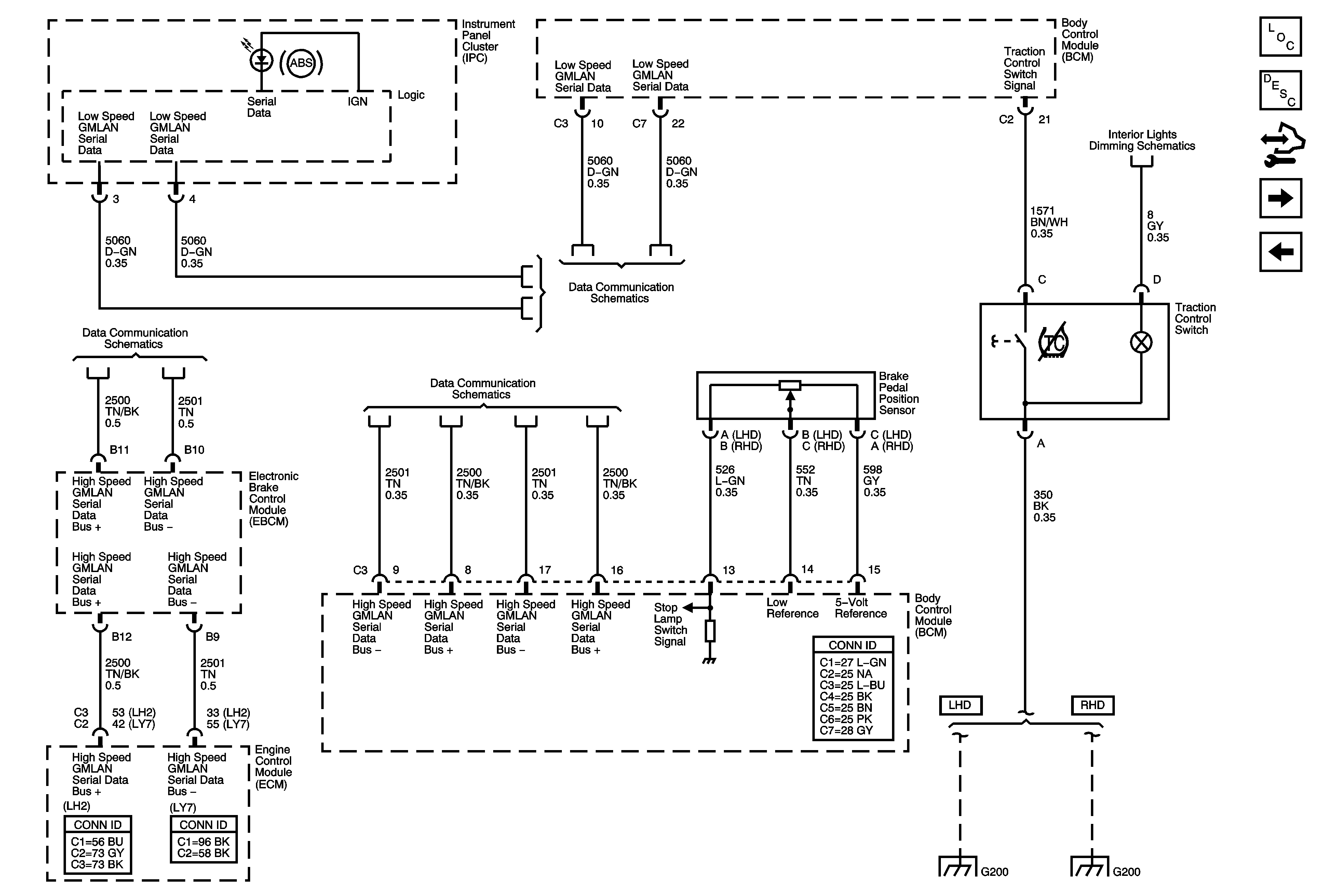
3:
Indicator, Traction Control, and Brake Pedal Position
Master Electrical Component List
ABS Description and Operation
Control Module References
Stability Control System and Brake Fluid Pressure Sensor
Wheel Speed Sensors
Dimming Lamps (1 of 3)
High Speed GMLAN
Low Speed GMLAN Serial Data 1 of 2
High Speed GMLAN
G200 (1 of 2) LHD
G200 2 OF 2 (RHD)
Figure
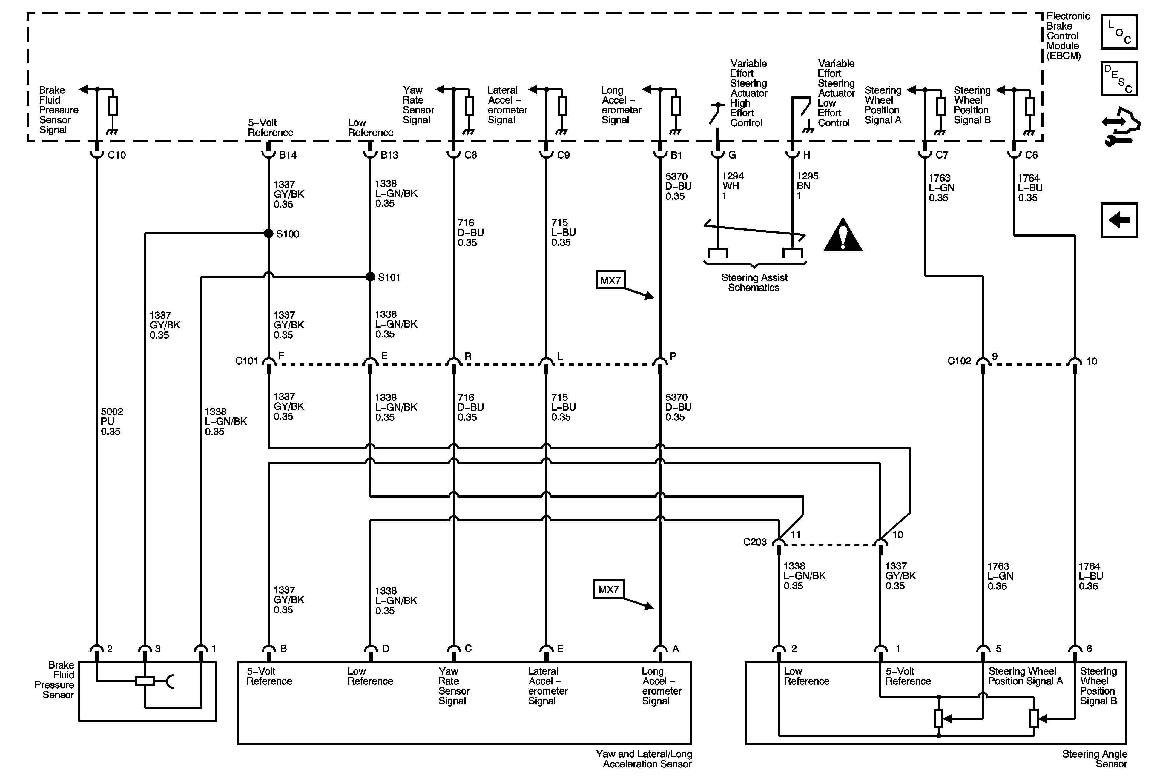
4:
Stability Control System and Brake Fluid Pressure Sensor
Master Electrical Component List
ABS Description and Operation
Control Module References
Indicator, Traction Control, and Brake Pedal Position Sensor
Antilock Brake System Schematic Icons
Variable Effort Steering Schematic