GM Service Manual Online
For 1990-2009 cars only
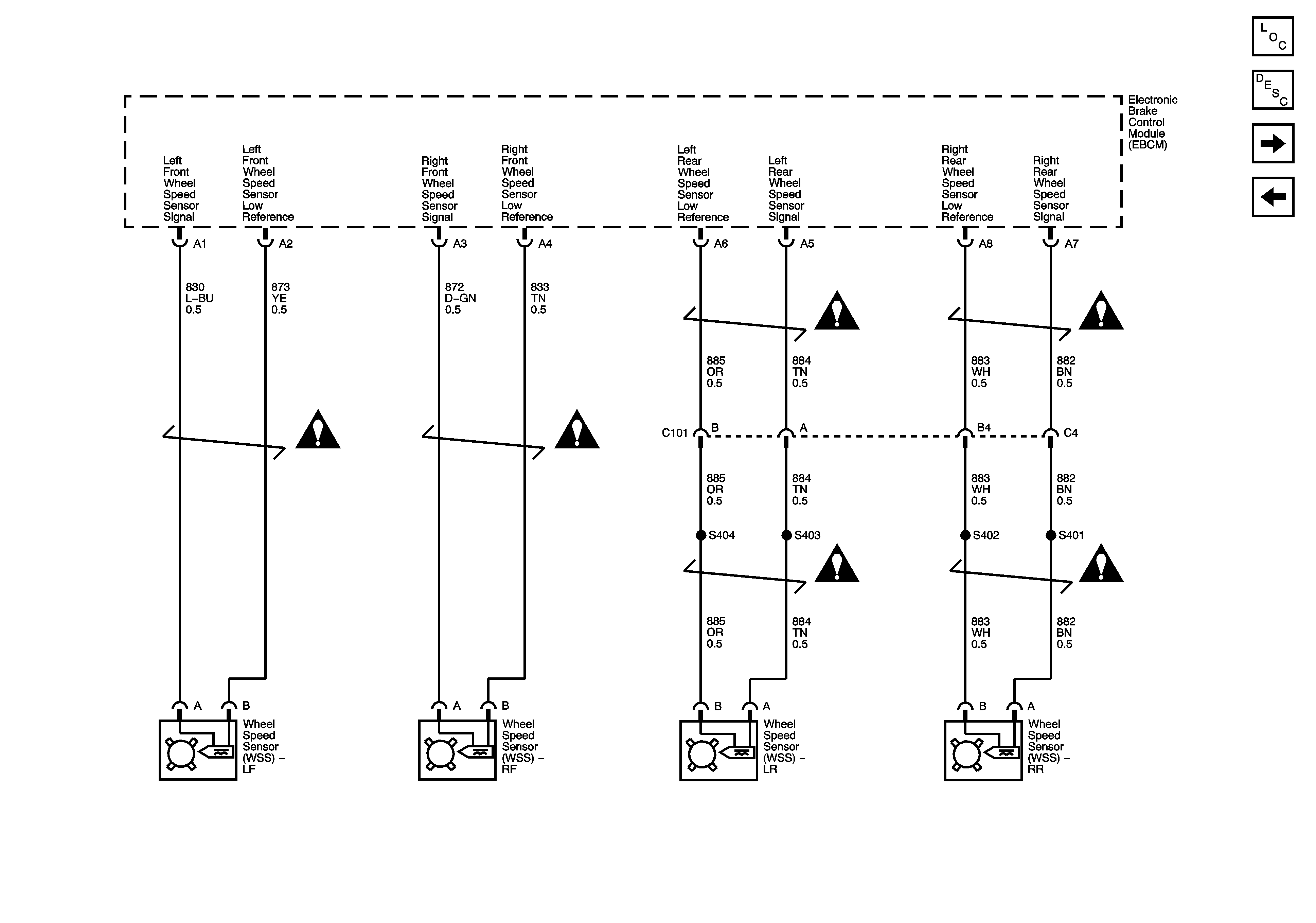
Figure 1:

Module Power, Ground and Serial Data


Object Number: 1220116  Size: FS
Master Electrical Component List
ABS Description and Operation
Wheel Speed Sensors
RIM and THEFT Fuses and Ignition Switch - 2 of 2
G104
Fuse Block - Underhood B+ Bus Schematic
ABS, STARTER RLY, STRG CTLS, TCM/IPC, and WASH NOZ Fuses
Class 2 Serial Data - 1 of 2
G104
G102, G105, G107, G108, G109 and G110
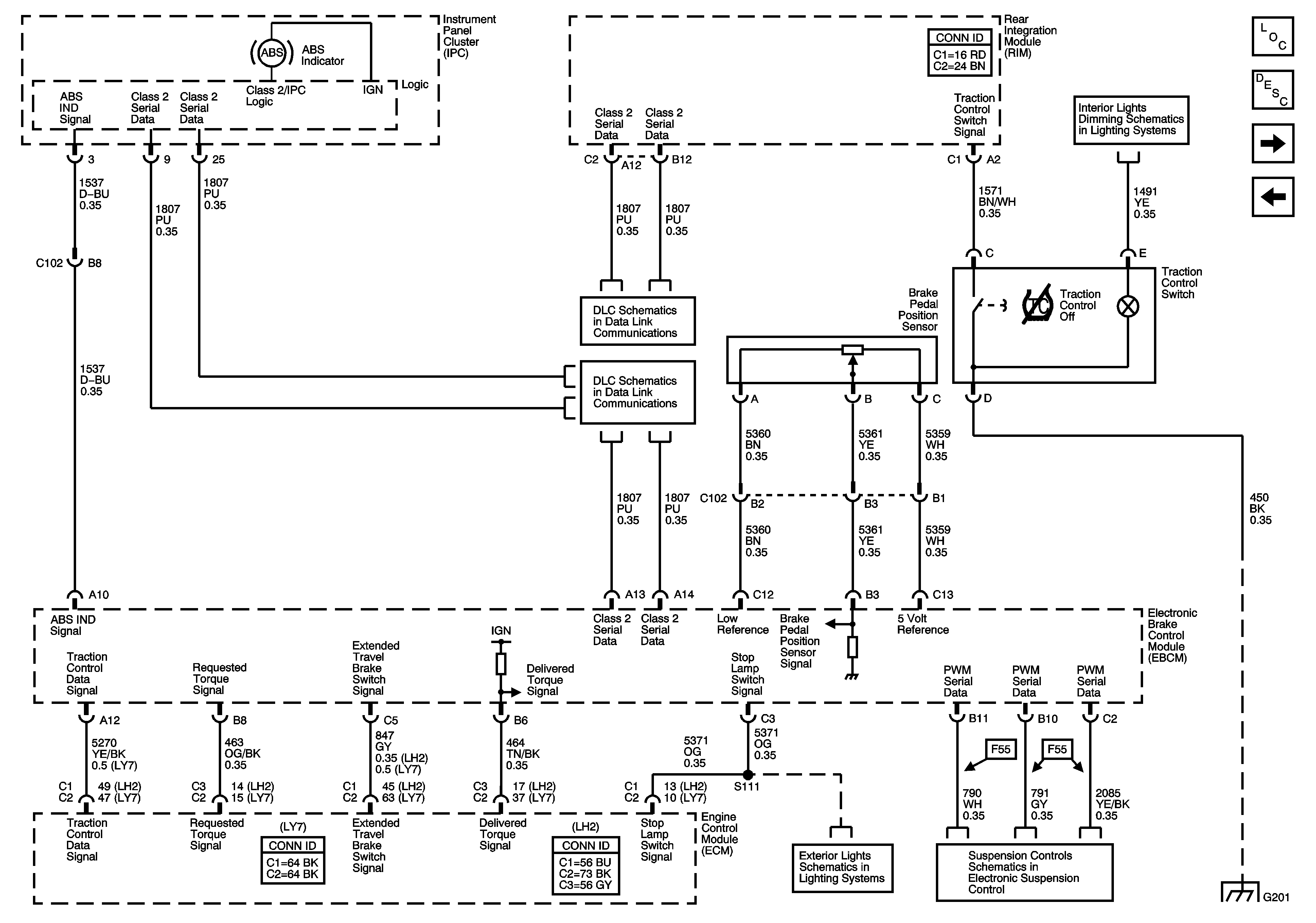
Figure 2:

Wheel Speed Sensors


Object Number: 1220122  Size: FS
Master Electrical Component List
ABS Description and Operation
Indicators, Traction Control, and Brake Pedal Position
Power, Ground and Serial Data
Antilock Brake System Schematic Icons
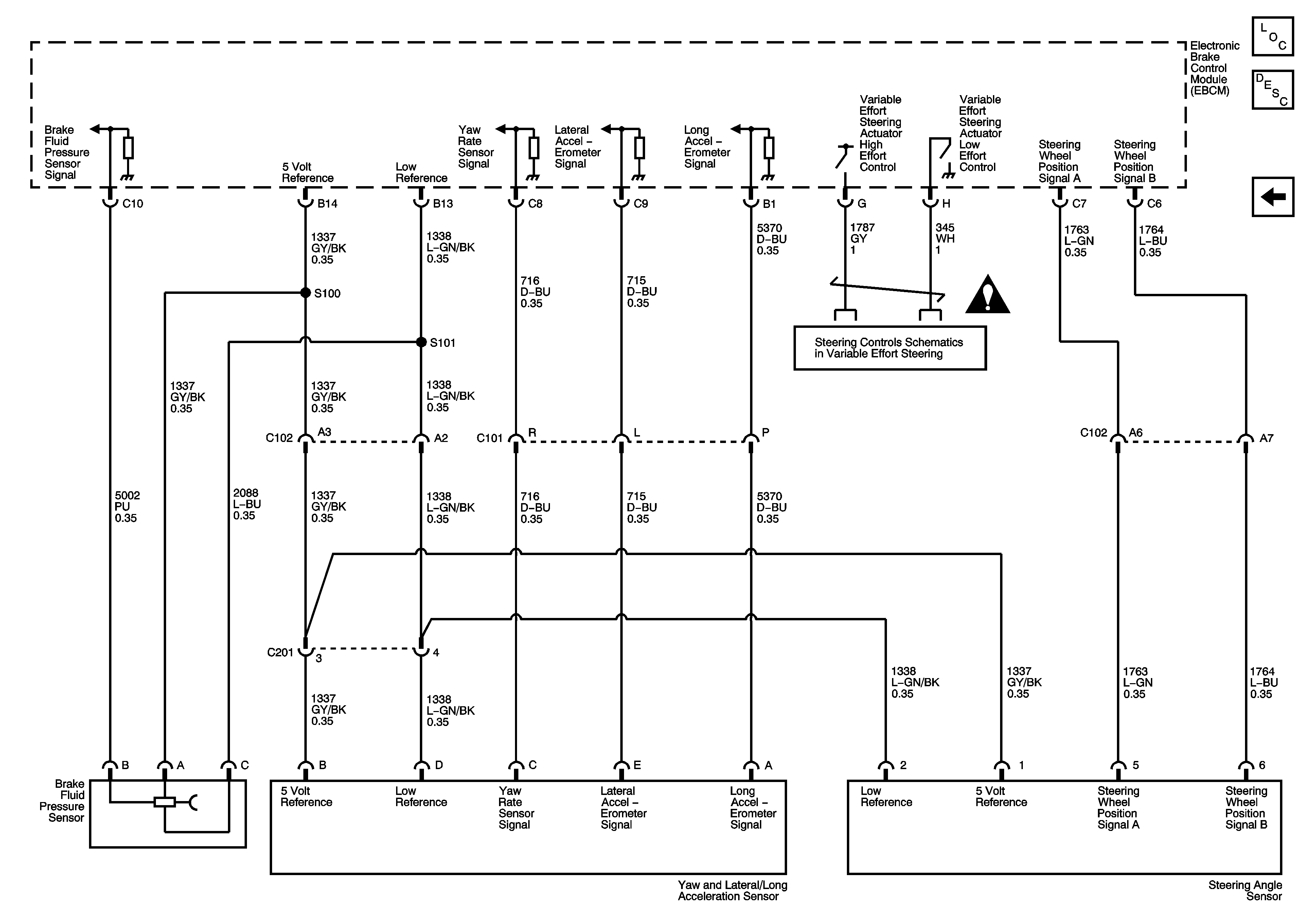
Figure 3:

Indicator, Traction Control, and Brake Pedal Position


Object Number: 1220125  Size: FS
Master Electrical Component List
ABS Description and Operation
Stability Control System and Brake Fluid Pressure Sensor
Wheel Speed Sensors
Dimming Lamps - 1 of 2
Class 2 Serial Data - 2 of 2
Class 2 Serial Data - 1 of 2
Tail Lamps (Domestic) Schematic
Power, Grounds, Serial Data and Controls
G201
Figure 4:

Stability Control System and Brake Fluid Pressure Sensor


Object Number: 1220129  Size: FS
Master Electrical Component List
ABS Description and Operation
Indicators, Traction Control, and Brake Pedal Position
Variable Effort Steering Schematic
Antilock Brake System Schematic Icons