Tools Required
| • | J-2619-A Slide Hammer w/Adapter |
| • | J 8107-2 Side Bearing Puller Pilot |
| • | J 22888-20A Universal Two Jaw Puller |
| • | J 29369-1 Bushing and Bearing Remover |
- Remove the bolts (16) and the dampener (300).
- Remove the drain plug (8) and the fill plug (6). Ensure all transfer case fluid is drained out of the transfer case.
- Remove the 17 case attaching bolts (11).
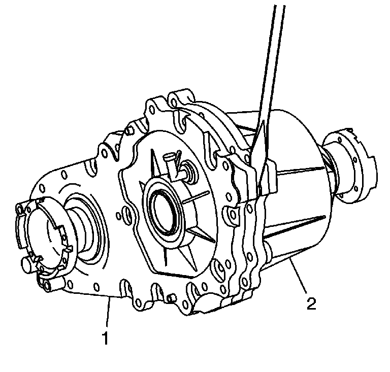
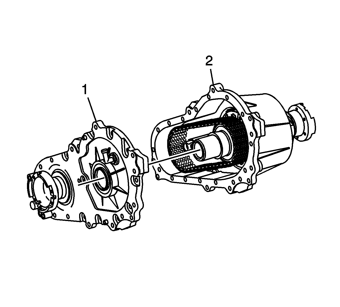
- Using a screwdriver at the pry points located on the case (1) and cover (2), pry the case (1) and cover (2) apart.
- Separate the case (1) and cover (2).
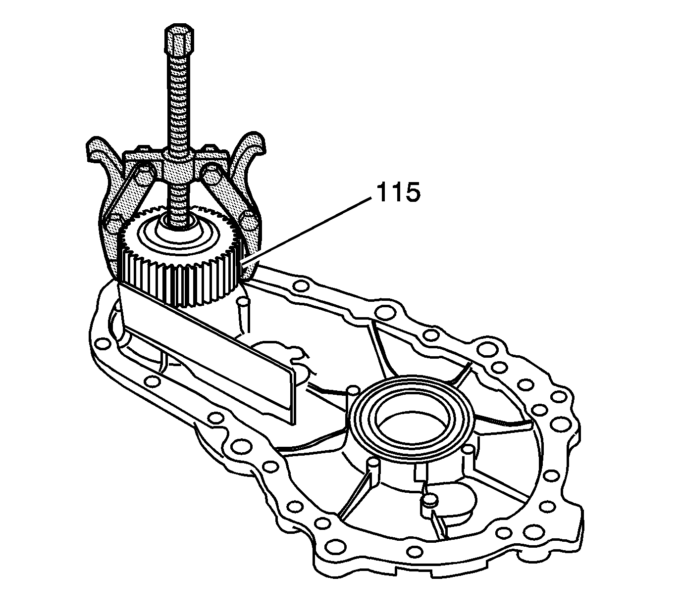
- Use the J 22888-20A to remove the lower sprocket (115).
- Remove the snap ring (114).
- Push the front output shaft (112) from the case (1).
- Remove the vent baffle bolt (9) and baffle (10) from the case (1).
- Remove chain snubber bolts (4) and snubber (3) from the case (1).
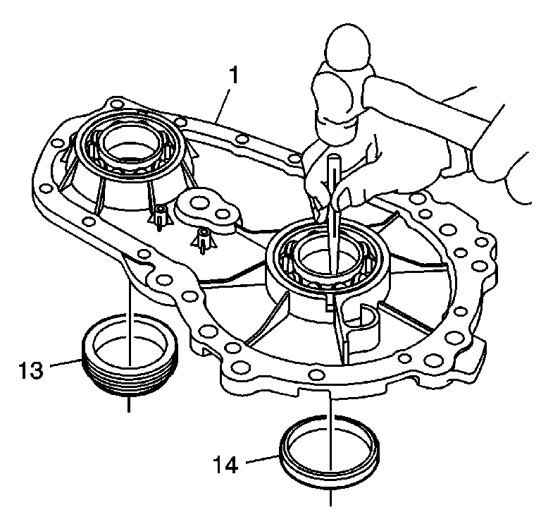
- Using a hammer and a suitable driver, remove the front output seal (13) and input seal (14) from the case (1).
- Using a hammer and a suitable punch, remove the front output bearing (113) and input bearing (117) if they are to be replaced.
- Remove the vent (15) and discard.
- Replace it with a NEW vent.
- Remove the chain (109) from the cover (2).
- Remove the planetary assembly and thrust washer (100) from the cover.
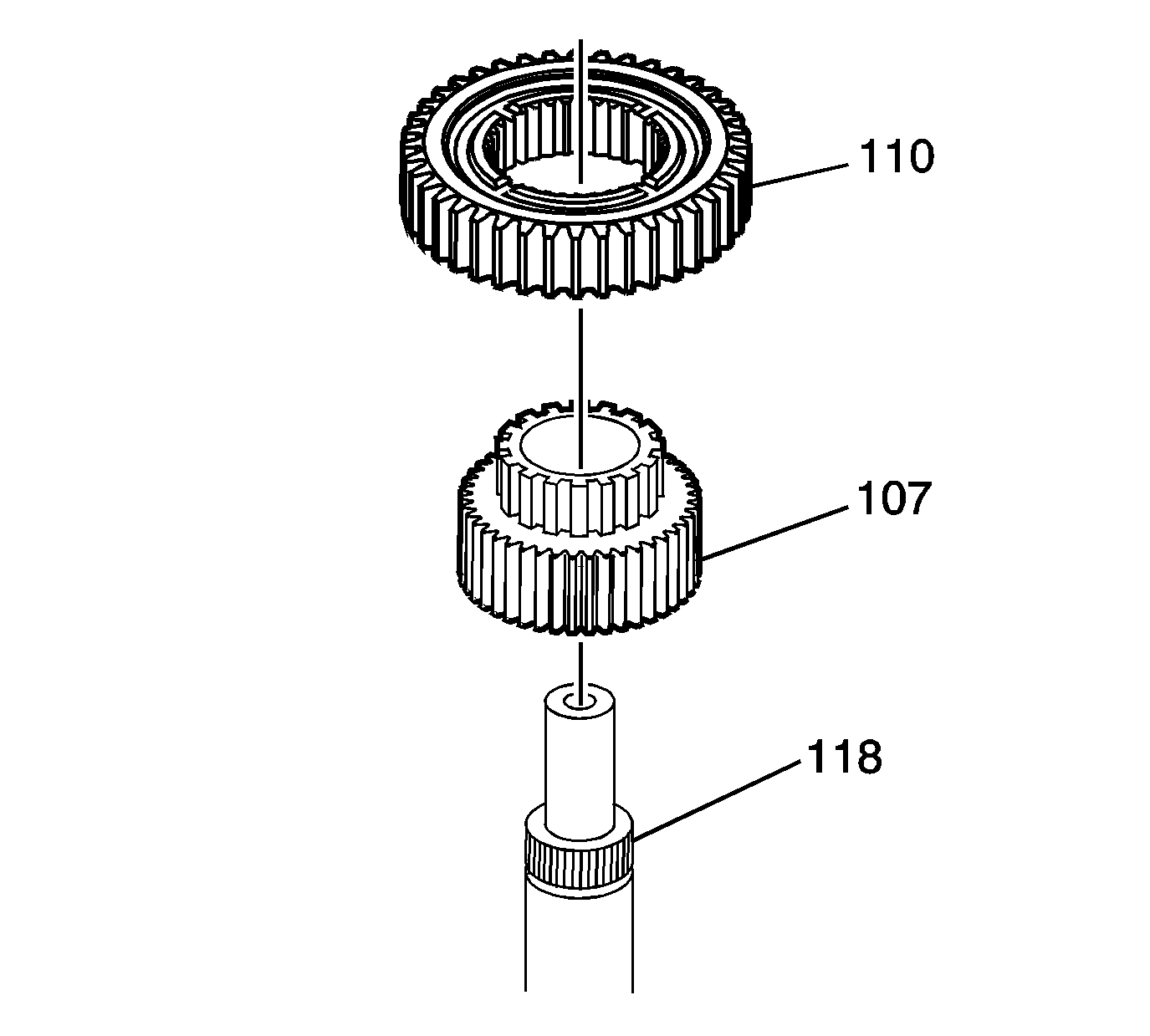
- Using a press, remove the input shaft assembly (118, 107 and 110) from the carrier (111).
- Note the direction of the carrier assembly (111). The groove around the splines for 50/50 and 40/60 ratios face toward the washer and output shaft.
- Note the orientation of the sun gear. The raised lip faces out.
- Remove the upper sprocket (107) and sun gear (110) from the input shaft (118).
- Using the J 22888-20A (1) and the J 8107-2 (2) , remove the sun gear (101) from the rear output shaft.
- Using snap ring pliers, remove the snap ring (102) from the output shaft (106).
- Push the output shaft (106) from the cover (2).
- Using a hammer and a suitable punch, from inside the cover, drive out the rear output seal (7) and the outside output bearing (104).
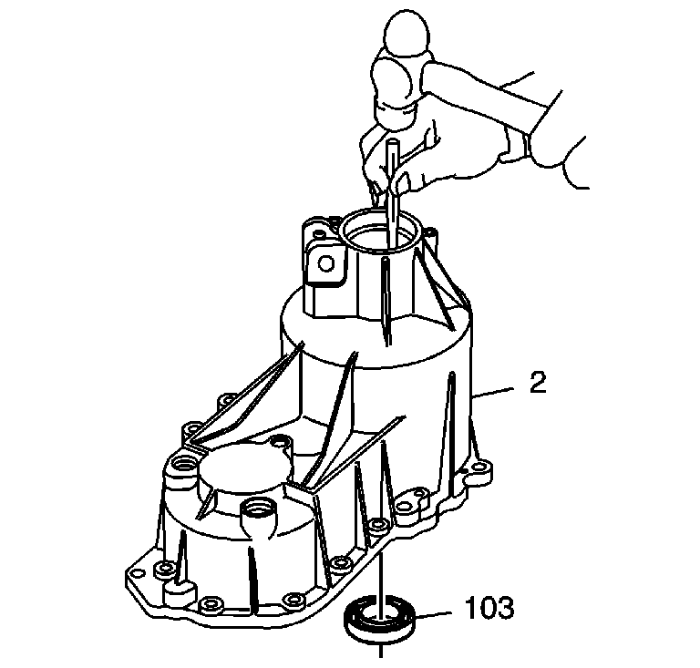
- Using a hammer and a suitable punch, from outside the cover (2), inside the output shaft bore, drive out the inner output shaft bearing (103).
- Using the J-2619-A (1) and the J 29369-1 (2), remove the front output cover bearing (116) from the cover.

Important: Service replacement assemblies supplied in 2007 and later may be a BW 4479 transfer case. Refer to Transfer Case Description and Operation and to the 2006 SRX Transfer Case Unit Repair Manual.


Important: To prevent thread damage, clean exposed bolt threads before removing bolts.
Notice: Refer to Machined Surface Damage Notice in the Preface section.


Notice: Refer to Transfer Case Seal Removal Notice in the Preface section.

Important: Only remove the bearings if they are to be replaced.

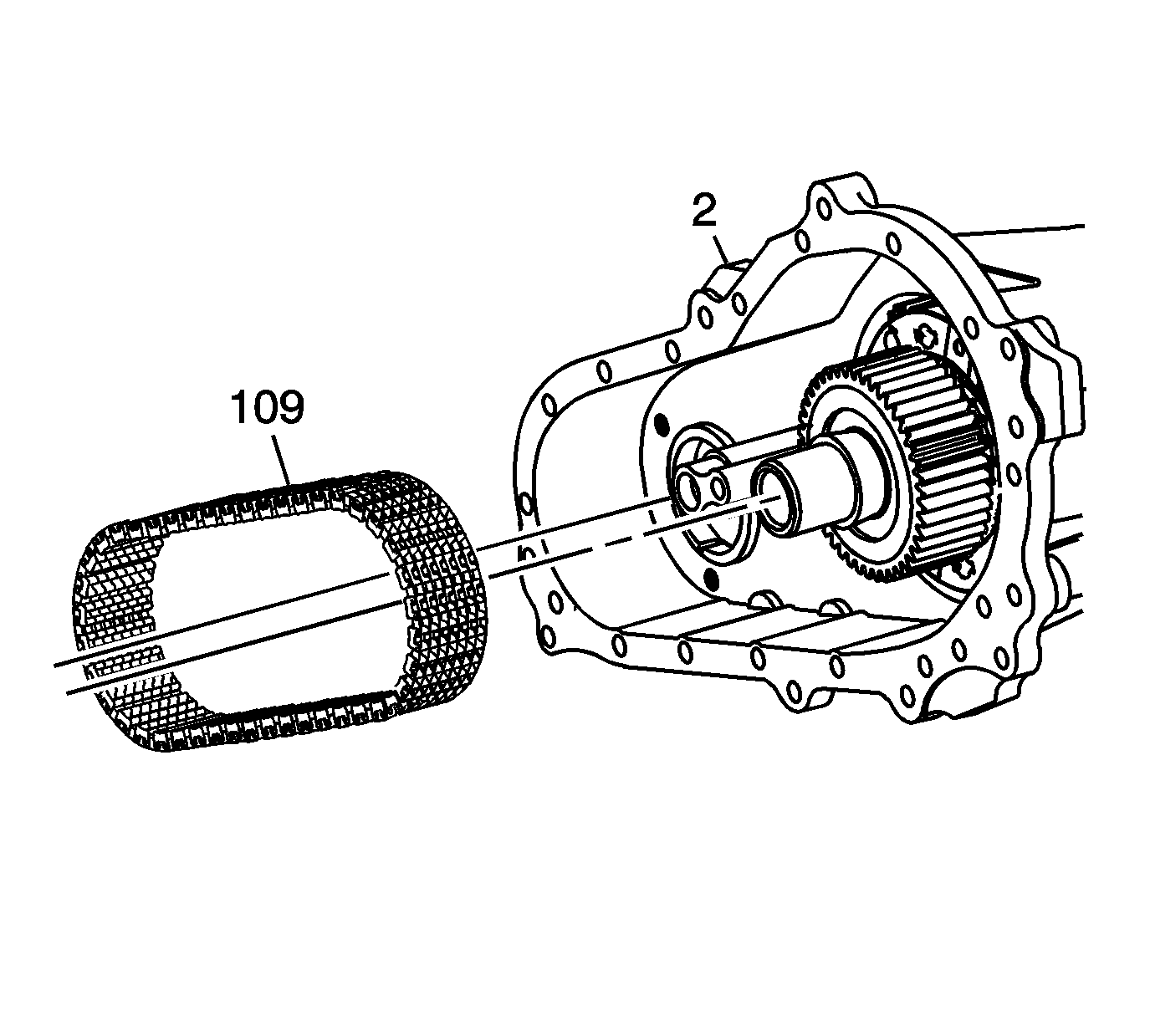
Important: If the chain and sprockets are to be used again, note the position of the blue chain link, in or out.
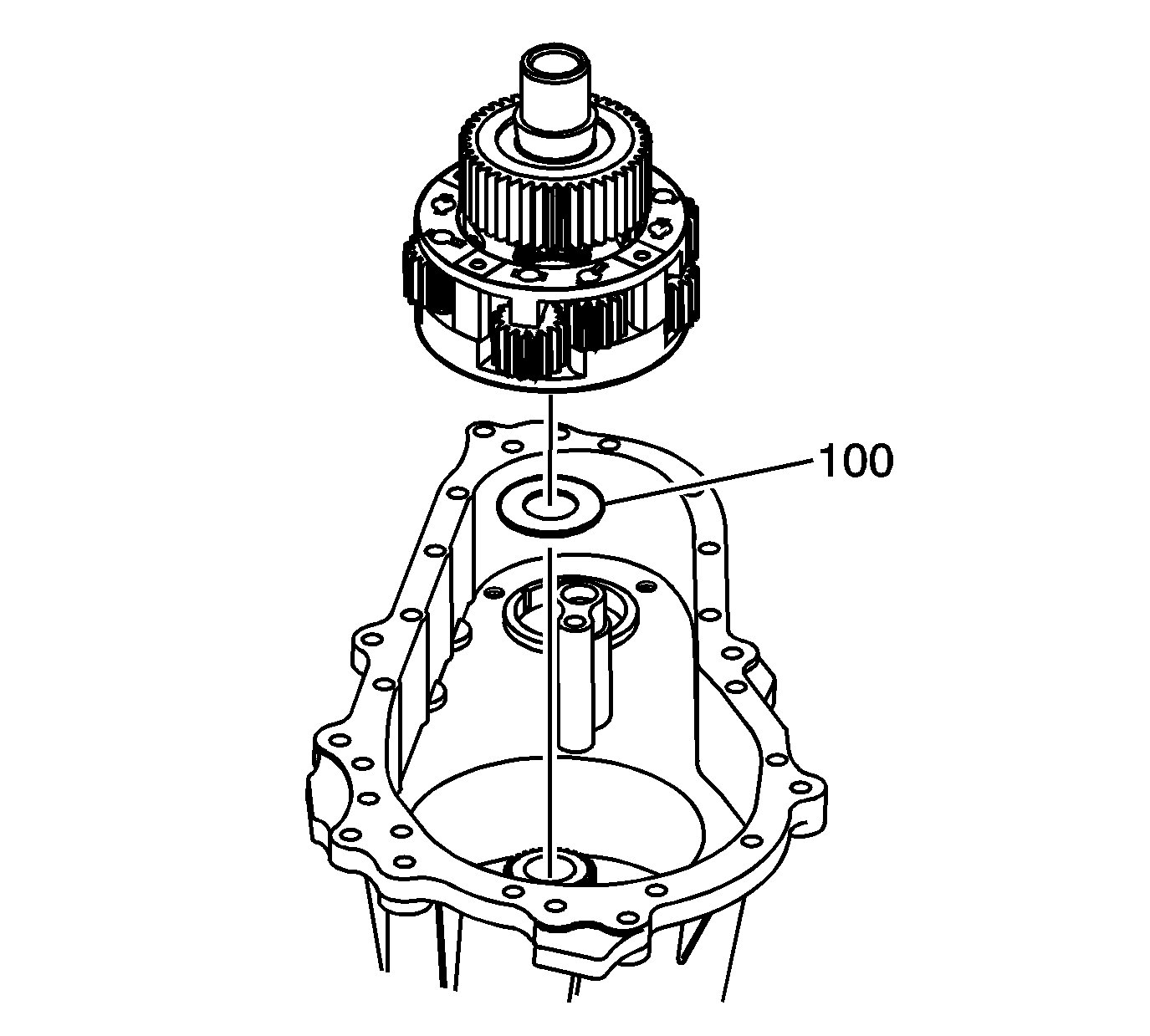

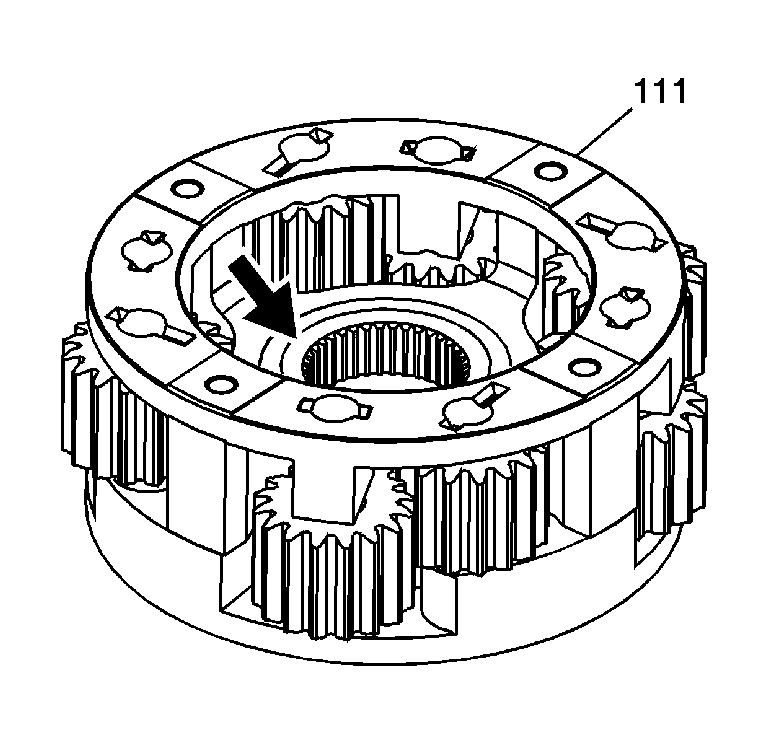
Important: The carrier assembly (111) can be installed with the groove around the splines to the drive sprocket. This will cause a mis-build.
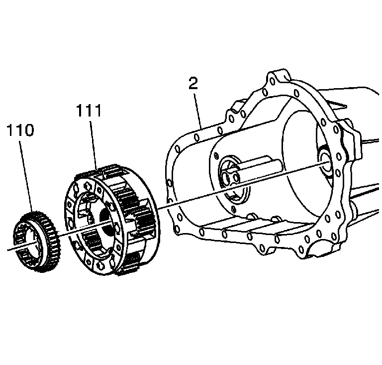


Notice: Refer to Transfer Case Seal Removal Notice in the Preface section.
Notice: Refer to Transfer Case Bearing Removal Notice in the Preface section.

Notice: Refer to Transfer Case Bearing Removal Notice in the Preface section.
Notice: Refer to Transfer Case Bearing Removal Notice in the Preface section.

