Schematic Reference: Engine Controls Schematics
Description
The Powertrain OBD system check is an organized approach to identifying a problem created by an electronic engine control system malfunction. The Powertrain OBD system check must be the starting point for any driveability complaint diagnosis. The Powertrain OBD system check directs the service technician to the next logical step in diagnosing a complaint. Do not perform this check if no driveability complaint exists. Understanding the table and using it correctly will reduce diagnostic time and prevent the replacement of good parts.
Important: This vehicle is equipped with a Powertrain Control Module (PCM) utilizing an Electrically Erasable Programmable Read Only Memory (EEPROM). When diagnostics call for replacement of the PCM, the new PCM must be programmed.
Refer to PCM Replacement/Programming
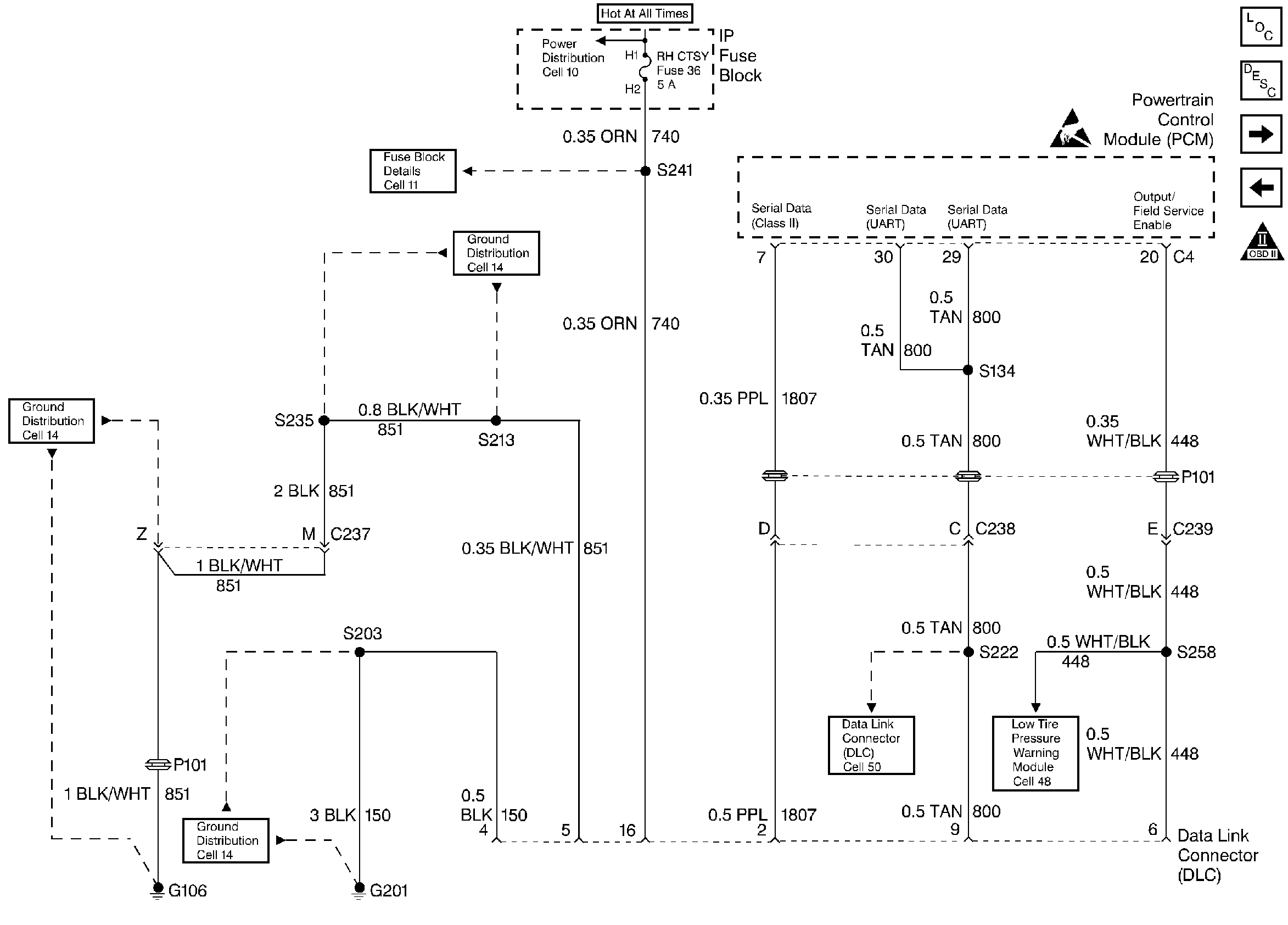
. Refer to
Data Link Connector - DLC

for schematic.
Test Description
Number(s) below refer to step numbers on the diagnostic table.
-
The diagnostic tables in this section are designed for use with a scan tool. If the scan tool is inoperative, this must be corrected before beginning any other diagnostic procedures. DO NOT Clear Info unless instructed by a diagnostic procedure.
-
If multiple DTCs are stored, diagnose in the following order of priority:
| 1. | PCM failure DTCs (P0601, P0602). |
| 2. | System Voltage DTCs. |
| 3. | Component level DTCs (Sensors, Solenoids, Relays etc.). Multiple DTCs within this category should be diagnosed in numerical order starting with the lowest numbered DTC. |
| 4. | System level DTCs (Misfire, Fuel Trim, etc.). |
Always Diagnose Last Tst Fail before History.
For Transmission DTCs, Refer to the Transmission Section 7A-14A.
Important: Checking for applicable service bulletins before proceeding with diagnosis is recommended
-
If a DTC is only in history, it may be beneficial to review Frez Frme Data and/or Fail Records. Use the odometer information and the fail counter to determine how frequently and how recently the DTC set. This information and the other operating conditions when the DTC set may help diagnose an intermittent problem. This is explained further in Symptoms .
-
Capturing stored info will preserve data that will be lost when instructed to Clear Info at the end of a diagnostic table, or if a PCM disconnect or replacement occurs during a diagnostic procedure. The data is stored in the scan tools memory. The captured info should be reviewed at the end of the diagnostic table to catch the next DTC in the event multiple DTCs were stored. Follow the order of priority as listed for Step 3 above.
-
Compare actual control system data with the values in the Engine Scan Tool Data List to determine if any parameter is not within limits. Keep in mind that a base engine problem (i.e. advanced cam timing) may substantially alter sensor values. If the actual data does not correspond with the values in the Engine Scan Tool Data List refer to the appropriate system/component diagnostic aids or test descriptions.
Step | Action | Value(s) | Yes | No |
|---|---|---|---|---|
Does the scan tool display data? | -- | Go to No Scan Tool Data | ||
2 | Does the engine start and run? | -- | ||
Using the scan tool, select Eng DTC, DTC Info, Last Tst Fail. Are any DTCs displayed? | -- | |||
Using the scan tool, select Eng DTC, DTC Info, History. Are any DTCs displayed? | -- | |||
Using the scan tool, select Capture Info, then Store Info (this option will only be displayed if there is no previously captured data) or Refresh Info (to overwrite older data with current info). Is the action complete? | -- | Go to the applicable DTC table | -- | |
Compare the scan tool data with the values shown in the Engine Scan Tool Data List Are the values normal or within typical ranges? | -- | Go to Symptoms | Go to Diagnostic Aids and Test Descriptions |
