For 1990-2009 cars only
- Park the vehicle on level ground.
- Inspect the tire pressure.
- Inspect the fuel level.
- Inspect the passenger compartment and the trunk in order to verify that no extra weight is in the passenger compartment or trunk.
- Place the front seat into the rear position.
- Bounce the vehicle three times at the front and rear in order to normalize the suspension.
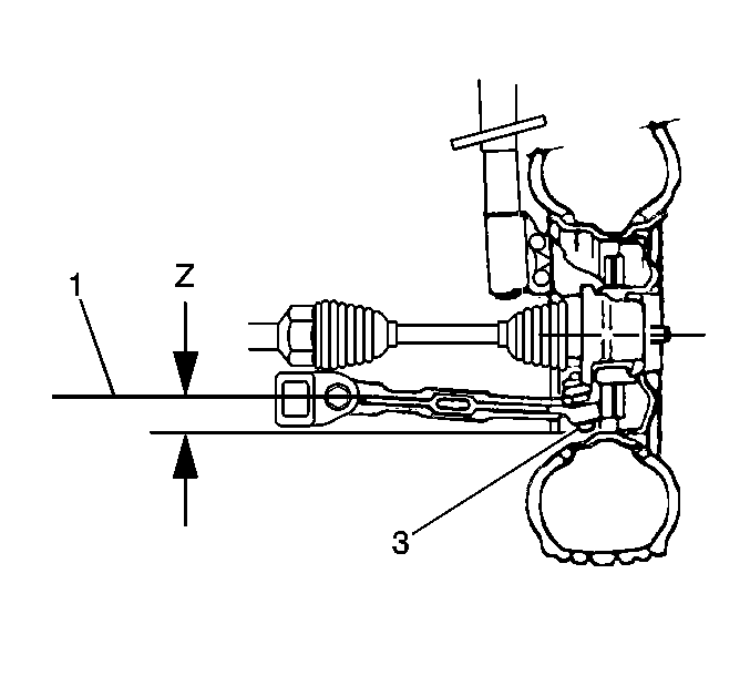
- Measure the clearance (Z) between the centerline of the bushing bolt and the lowest point on the ball joint housing (3) (excluding the grease fitting).
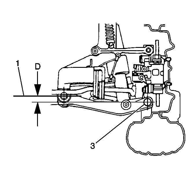
- Measure the clearance (D) between the centerline of the front inner bearing bushing bolt (3) and the centerline of the front outer bushing bolt (this measurement should be taken on the front side of the rear suspension assembly).
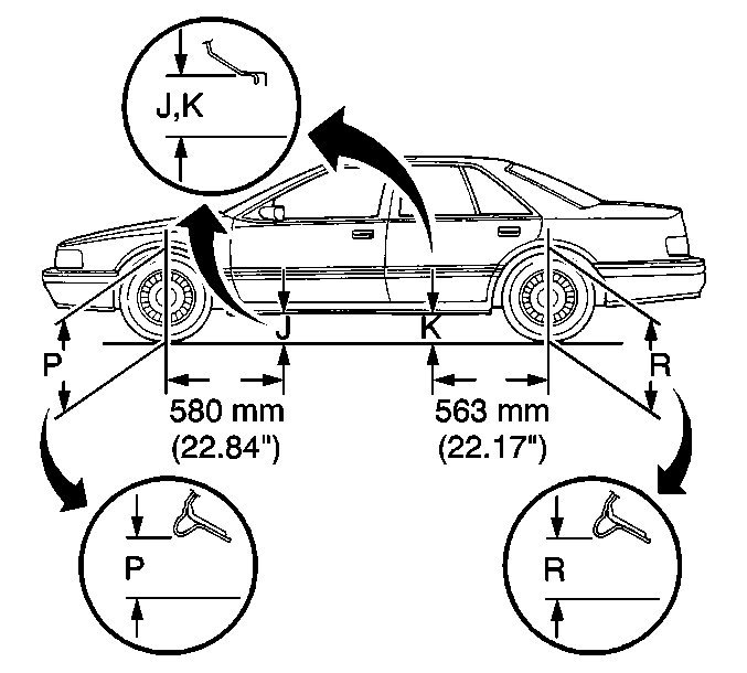
- Measure the clearances (P-R) between the underbody and the ground.
- Verify that all of the above clearances measure within the maximum variation from the specified values.
Verify that all of the tires are inflated to the proper pressure.
The fuel tank should be full.
The trunk must be empty except for the spare tire and jack. On vehicles equipped with Electronic Level Control (ELC), verify that the Electronic Control Level (ELC) operates properly.

The clearance (Z) should measure 50 mm (1.97 in).

The clearance (D) should measure 29 mm (1.14 in).

The clearance (P) should measure 715 mm (28.15 in).
The clearance (J) should measure 220 mm (8.66 in).
The clearance (K) should measure 214 mm (8.43 in).
The clearance (R) should measure 709 mm (27.91 in).
All measurements are plus or minus 10 mm (0.04 in).
Maximum variation side-to-side is 12 mm (0.05 in).
