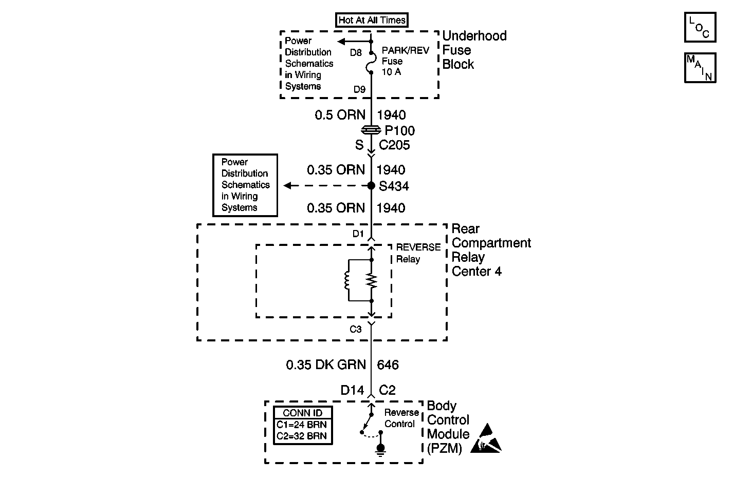
Circuit Description
When the body control module (PZM) receives a class 2 serial data message that the transaxle is in reverse, the PZM energizes the reverse lamp relay and the backup lamps are turned on. When the PZM has not commanded the backup lamps on, the voltage at connector C2 terminal D14 is measured every 1000 ms.
Conditions for Setting the DTC
The PZM determines the voltage at connector C2 terminal D14 is approximately equal to ground.
DTC Will Clear When
The PZM determines the voltage at connector C2 terminal D14 is greater than ground for at least 1 monitoring cycle.
Step | Action | Value(s) | Yes | No |
|---|---|---|---|---|
1 | Did you perform the Lighting Systems Diagnostic System Check? | -- | Go to Step 2 | |
2 | With the transmission in the PARK position, measure resistance of CKT 646 from Reverse Relay terminal C3 to a known good ground. Is the measured resistance within the specified range? | 0-5 ohms | Go to Step 3 | Go to Step 4 |
3 | Repair a short to ground on CKT 646 between the Reverse Relay and Body Control Module (PZM). Is the repair complete? | -- | Go to Step 5 | -- |
4 | Replace the Body Control Module (PZM). Refer to Body Control Module Replacement in Body Control Systems. Is the replacement complete? | -- | Go to Step 5 | -- |
5 |
Does the DTC reset? | -- | Go to Step 2 | System OK. |
