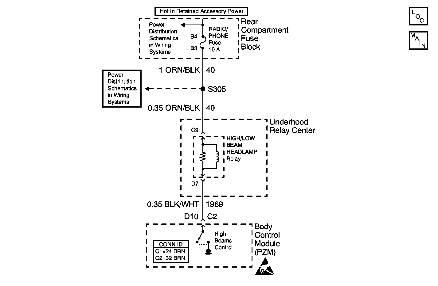
Circuit Description
The PZM commands the high beams through a discrete output to the high/low beam headlamp control relay. When the headlamps relay is energized the high/low beam headlamp control relay provides a power source to either the low beams or the high beams.
Conditions for Setting the DTC
The commanded state of the high beams does not match the feedback state.
Action Taken When the DTC Sets
The PZM continues to command the state requested until the instrument cluster revokes the request.
When the measurements are requested in the diagnostic table below, use the J 39200 Digital Multimeter (DMM) with the correct terminal adapter from the J 35616 .
When a proper connection is requested, refer to Testing for Intermittent Conditions and Poor Connections in Wiring Systems.
When a wire, connector or terminal repair is requested, use the J-38125 . Refer to Wiring Repairs in Wiring Systems.
Step | Action | Value(s) | Yes | No |
|---|---|---|---|---|
1 | Did you perform the Lighting Systems Diagnostic System Check? | -- | Go to Step 2 | |
2 |
Is battery voltage measured? | -- | Go to Step 3 | Go to Step 7 |
3 | Measure voltage from the high/low beam headlamp relay terminal C9 (ORN/BLK) to terminal D7 (BLK/WHT) Is battery voltage measured? | -- | Go to Step 4 | Go to Step 5 |
4 | Replace the high/low beam headlamp relay. Is the repair complete? | -- | Go to Step 9 | -- |
5 | Inspect CKT 1969 (BLK/WHT) for an open. Refer to Testing for Continuity in Wiring Systems. Is CKT 1969 OK? | -- | Go to Step 6 | Go to Step 8 |
6 | Replace the PZM. Refer to Body Control Module Replacement in Body Control Systems. Is the repair complete? | -- | Go to Step 9 | -- |
7 | Repair the open or short to ground in CKT 40 (ORN/BLK). Refer to Wiring Repairs in Wiring Systems. Is the repair complete? | -- | Go to Step 9 | -- |
8 | Repair the suspect wiring. Refer to Wiring Repairs in Wiring Systems. Is the repair complete? | -- | Go to Step 9 | -- |
9 |
Does the DTC reset? | -- | Go to Step 2 | System OK. |
