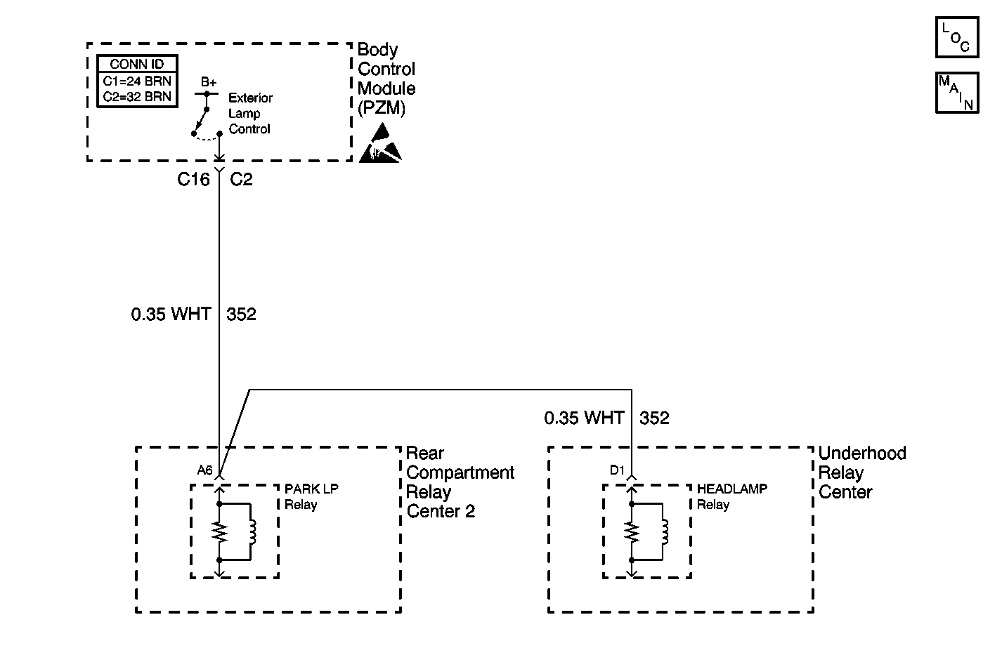
Circuit Description
When the exterior lamps are commanded ON, the PZM energizes the headlamp relay and the parklamp relay through PZM connector C2 terminals C9 and C6, respectively. Power for these relays is also provided by the PZM through connector C2 terminal C16. Every 300 ms, the PZM determines the voltage at these terminals and compares it to the commanded state.
Conditions for Setting the DTC
The exterior lamps are commanded on for at least 300 ms and the exterior lamp power is low for at least 2 consecutive monitoring cycles.
Action Taken When the DTC Sets
The PZM commands the exterior lamps OFF and attempt to turn the lamps ON every 1200 ms until the exterior lamps are no longer required.
Conditions for Clearing the DTC
The exterior lamps are commanded ON and the exterior lamp power is active after 2 consecutive monitoring cycles.
When the measurements are requested in the table below, use the J 39200 Digital Multimeter (DMM) with the correct terminal adapter from J 35616 .
When a proper connection is requested, refer to Testing for Intermittent Conditions and Poor Connections in Wiring Systems.
When a wire, connector or terminal repair is requested, use J-38125 . Refer to Wiring Repairs in Wiring Systems.
Test Description
The number(s) below refer to the step number(s) on the diagnostic table.
Step | Action | Value(s) | Yes | No |
|---|---|---|---|---|
1 | Did you perform the Lighting System Diagnostic System Check? | -- | Go to Step 2 | |
Is the resistance less than or equal to the specified value? | 5 ohms | Go to Step 4 | Go to Step 3 | |
3 | Replace the PZM. Refer to Body Control Module Replacement in Body Control Systems. Is the repair complete? | -- | Go to Step 5 | -- |
4 | Repair the short to ground in CKT 352 (WHT). Refer to Wiring Repairs in Wiring Systems. Did you complete the repair? | -- | Go to Step 5 | -- |
5 |
Does the DTC reset? | -- | Go to Step 2 | System OK. |
