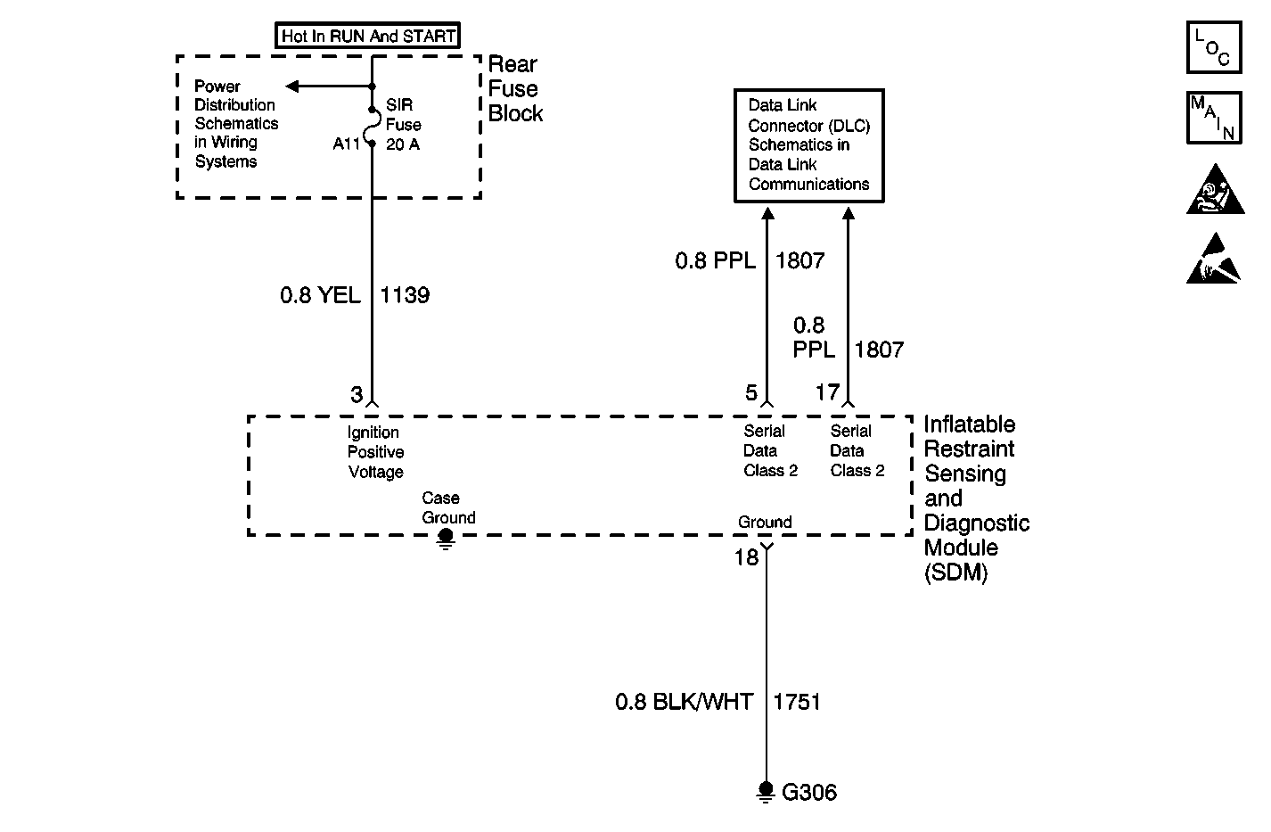
Circuit Description
When you first turn ON the ignition, the inflatable restraint sensing and diagnostic module (SDM) performs tests to diagnose critical malfunctions within itself. Then SDM learns the soure ID of the battery voltage report message. The SDM monitors this message every 300 milliseconds to determine if it is within a valid operating range.
Conditions for Running the DTC
The SDM monitors the Class 2 serial data line during the continuous monitoring for the battery voltage, the voltage must stay within the normal operating voltage range (9.5 volts-15.5 volts).
Conditions for Setting the DTC
The ignition positive voltage level is greater than 15.5 volts for approximately 1.2 seconds or more.
Action Taken When the DTC Sets
The SDM sets a DTC and disables the following State of Health (SOH) DTCs:
| • | DTC U1096 |
| • | DTC U1255 |
| • | DTC U1300 |
| • | DTC U1301 |
The SDM will not command the AIR BAG warning lamp ON for this DTC.
Conditions for Clearing the DTC
| • | The battery positive voltage level is less than 15.5 volts for approximately 1.2 seconds. |
| • | You can issue a CLEAR CODES command |
Diagnostic Aids
This DTC may set when the vehicle is placed on a battery charger, on fast charge, for a long period of time.
Test Description
The numbers below refer to the step numbers on the diagnostic table:
-
Perform the SIR Diagnostic System Check before continuing with the diagnosis of this DTC.
-
This test checks for proper voltage being recieve by the SDM.
-
This test checks whether the malfunction is in the charging system or the SDM.
Step | Action | Value(s) | Yes | No |
|---|---|---|---|---|
Did you perform the Diagnostic System Check? | -- | Go to Step 2 | ||
Does the scan tool indicate that the voltage measure is less than the specified value? | 15.5 V | Go to Step 4 | Go to Step 3 | |
Does the voltage measure greater than the specified value? | 15.5 V | Go to Diagnostic System Check - Engine Electrical in Engine Electrical | Go to Step 4 | |
4 | Replace the SDM. Refer to Inflatable Restraint Sensing and Diagnostic Module Replacement . Did you complete the replacement? | -- | Go to Step 5 | -- |
5 |
Did you complete the action? | -- | -- |
