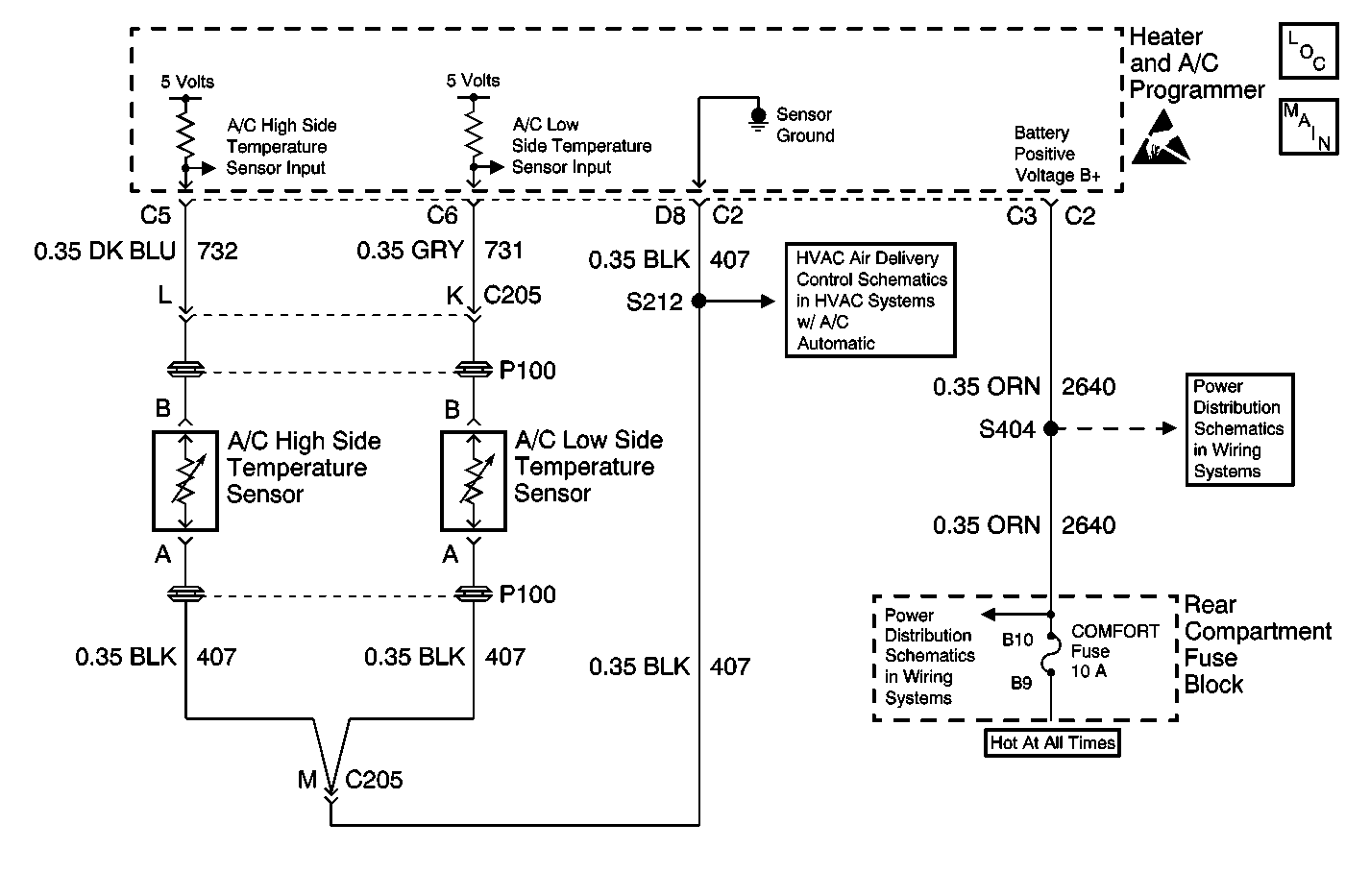
Circuit Description
In the process of controlling the compressor clutch, the heater and A/C programmer monitors certain inputs for an indication of a low refrigerant charge. If the system refrigerant state of charge falls below approximately 1/4 capacity, the heater and A/C programmer is capable of detecting this condition. The programmer will display VERY LOW REFRIGERANT--A/C COMPRESSOR OFF on the driver information center (DIC) in order to warn the operator.
The heater and A/C programmer determines the state of the charge by monitoring the temperature change in the low temperature sensor during the compressor engagement. This temperature drop is referenced by the heater and A/C programmer as a function of the ambient air temperature. If the refrigerant charge is too low, the refrigerant boils instantaneously after passing through the orifice tube. This action creates a large rapid change in the low temperature sensor reading. After several incidents are counted, the heater and A/C programmer sets DTC B1347. The message VERY LOW REFRIGERANT--A/C COMPRESSOR OFF will be displayed on the DIC. If a DTC B1347 is set, the compressor clutch disengages and remains disengaged until DTC B1347 is cleared. DTC B1347 may repeat if excessive pressure exists in the A/C charging station tank. Repair the A/C charging station before properly diagnosing DTC B1347.
Failure Conditions
The low side refrigerant temperature drops too quickly during several of the compressor cycles.
Action Taken When the DTC Sets
| • | The system disables the A/C compressor until the DTC is cleared. |
| • | The system displays the VERY LOW REFRIGERANT--A/C COMPRESSOR OFF message on the DIC. |
Test Description
-
Perform the HVAC Diagnostic System Check before continuing with the diagnosis of this DTC.
-
This test inspects for an intermittent open or short in the A/C Low Side Temp Sensor circuit.
-
This test verifies that the sensor is receiving the reference voltage.
Step | Action | Value(s) | Yes | No |
|---|---|---|---|---|
Did you perform the HVAC diagnostic system check? | -- | Go to Step 2 | Go to Diagnostic System Check | |
Does the scan tool indicate the temperature status is okay? | -- | Go to Testing for Intermittent Conditions and Poor Connections in Wiring Systems | Go to Step 3 | |
Does the voltage measure near the specified value? | 5 V | Go to Step 4 | Go to Step 5 | |
4 | Measure the voltage from the A/C low side temperature sensor signal circuit to the A/C low side temperature sensor ground circuit. Does the voltage measure near the specified value? | 5 V | Go to Step 7 | Go to Step 6 |
5 | Test the signal circuit of the A/C low side temperature sensor. For a short or an open. Refer to Testing for Intermittent Conditions and Poor Connections and Connector Repairs in Wiring Systems. Did you find and correct the condition? | -- | Go to Step 11 | Go to Step 8 |
6 | Test the ground circuit of the A/C low side temperature sensor for a high resistance or an open. Refer to Circuit Testing and Wiring Repairs in Wiring Systems. Did you find and correct the condition? | -- | Go to Step 11 | Go to Step 8 |
7 | Inspect for poor connections at the harness connector of the A/C low side temperature sensor. Refer to Testing for Intermittent Conditions and Poor Connections and Connector Repairs in Wiring Systems. Did you find and correct the condition? | -- | Go to Step 11 | Go to Step 9 |
8 | Inspect for poor connections at the harness connector of the heater and A/C programmer. Refer to Testing for Intermittent Conditions and Poor Connections and Connector Repairs in Wiring Systems. Did you find and correct the repair? | -- | Go to Step 11 | Go to Step 10 |
9 | Replace the A/C low side temperature sensor. Refer to Temperature Sensor Replacement - Low Side . Did you complete the repair? | -- | Go t o Step 11 | -- |
10 | Replace the heater and A/C programmer. Refer to Programmer Replacement . Did you complete the repair? | -- | Go to Step 11 | -- |
11 |
Does the DTC reset? | -- | Go to Step 2 | System OK |
