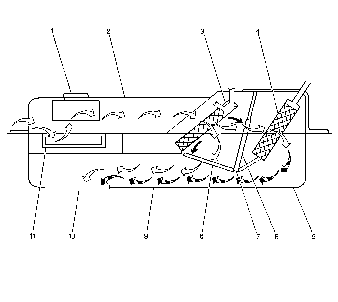
The heating and air conditioning module (2) incorporates most of the air delivery components into 1 assembly.
The air, which is utilized by the system, is drawn into the module through an opening at the base of the windshield. This air is then routed to the blower (1). The blower directs the air through the evaporator core (3). The air is cooled and dehumidified.
The air is then heated as required by passing through and around the heater core (4). Depending upon the mode selected, this air is then directed by the air valves (7) to the following locations:
| • | The A/C outlets in the instrument panel |
| • | The heater outlets at floor level |
| • | The defroster outlets |
The air exits from the interior by passing through the air exhaust grilles located in either of the following locations:
| • | The door lock pillars |
| • | The rear quarter |
Air Intake
The air intake (11) is directed by the air inlet valve.
The vacuum actuator controls the position of the valve. The air inlet valve has 2 positions. With no vacuum supplied to the actuator, the valve blocks off the recirculating air opening in order to allow only outside air to enter the blower.
When vacuum is supplied to the actuator, the valve blocks most of the outside air in order to allow the recirculation of approximately 90 percent of the total air supply from the blower.
Air Distribution
Air is directed into the air distributor assembly (9) through an up/down valve (7). The air is then directed to the following outlets:
| • | The heater outlets |
| • | The instrument outlets |
| • | The defroster outlets |
A vacuum actuator operates the 3-position up/down valve (7) . In the middle position, the valve allows the air to flow to the heater outlets and up through the instrument panel or defroster outlets.
When the vacuum is supplied, the valve is pulled downward (6). This allows the air to flow upward through the air distributor to the instrument panel or defroster outlets.
When the valve is pulled upward (8), the air flows through the heater outlets (4). In all 3 positions, a small amount of the air is directed to the following locations:
| • | The side window defroster outlets |
| • | The rear seat outlets |
The A/C defroster valve directs the air through the instrument panel or defroster outlets.
A vented valve blocks the airflow to the A/C outlets and directs the air to the windshield. With vacuum supplied, the valve moves forward to the actuator, directing the air to the A/C outlets.
Air conditioning Outlets
The following outlets may be adjusted in order to direct or shut off air flow:
| • | The 2 center outlets |
| • | The left and the right instrument panel outlets |
A small amount of air is directed to the side window defroster and heater outlets.
Defroster Duct
A unitized defroster outlet directs the air to both sides of the windshield. The outlet is attached to the top of the A/C module. The outlet is located on the top of the instrument panel.
Heater Outlet
The heater outlet is located along the bottom of the A/C module, near the center of the underside of the instrument panel. The outlet directs air to the floor heater ducts and to the rear seating area.
Rear Seat Outlet
Two rear seat outlets are located on either of the following locations:
| • | The back of the console |
| • | The back of the front seat armrest |
The outlets are independently adjustable.
