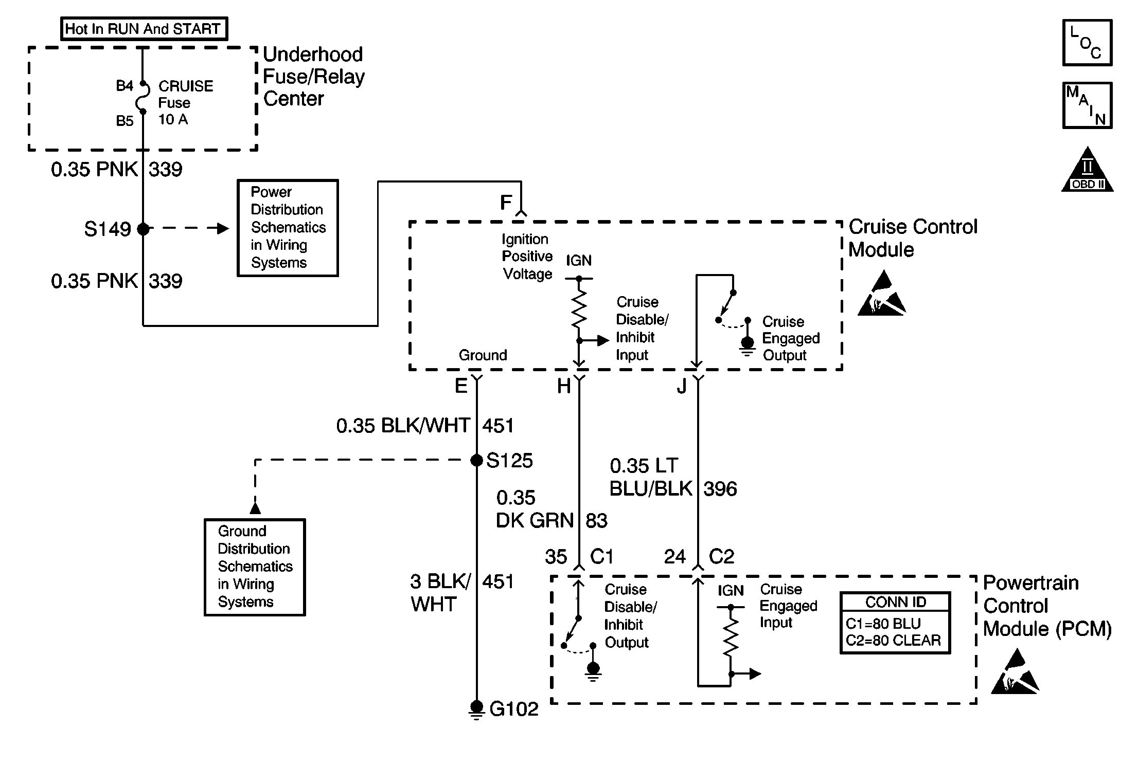
Circuit Description
The powertrain control module (PCM) uses output driver modules (ODMs) to control many functions of the engine, and the transaxle. The ODMs supply the ground path for the PCM controlled device when the PCM commands the device ON. Each ODM is able to control several outputs. The PCM monitors the ODMs for circuit conditions that are incorrect for the commanded state of the ODM. If the PCM detects an improper circuit condition in the ODM that controls the Cruise Inhibit Control Circuit, DTC P1585 will set.
Conditions for Running the DTC
| • | The engine is running. |
| • | System voltage is between 8 and 16 volts. |
Conditions for Setting the DTC
| • | The PCM detects an improper voltage level on the output circuit that controls the Cruise Inhibit Control Circuit. |
| • | The condition exists for at least 10 seconds. |
Action Taken When the DTC Sets
| • | The PCM will not illuminate the malfunction indicator lamp (MIL). |
| • | The PCM will store the conditions present when the DTC set as Failure Records data only. |
Conditions for Clearing the MIL/DTC
| • | The history DTC will clear after 40 consecutive warm-up cycles have occurred without a malfunction. |
| • | The DTC can be cleared by using the scan tool Clear DTC Information function. |
Diagnostic Aids
To determine whether an improper voltage level exists on the output circuit, the PCM compares the voltage level to the commanded state. For example, a failure condition exists if the PCM detects a low voltage level when the device is commanded OFF, or a high voltage level when the device is commanded ON.
If the condition is intermittent, refer to Intermittent Conditions in Symptoms.
Test Description
The numbers below refer to the step numbers on the diagnostic table.
-
Normally, ignition feed voltage should be present on the control circuit with the PCM disconnected and the ignition turned ON.
-
Tests for a short to voltage on the control circuit.
Step | Action | Value(s) | Yes | No |
|---|---|---|---|---|
1 | Did you perform the Powertrain On Board Diagnostic (OBD) System Check ? | -- | Go to Step 2 | |
Does the voltage measure near the specified value? | B+ | Go to Step 3 | Go to Step 4 | |
Does the test lamp illuminate? | -- | Go to Step 7 | Go to Step 5 | |
4 | Test the cruise inhibit control circuit for an open or short to ground. Refer to Wiring Repairs and Circuit Testing in Wiring Systems. Did you find and correct the condition? | -- | Go to Step 10 | Go to Step 6 |
5 | Inspect for poor connections at the harness connector of the PCM. Refer to Testing for Intermittent Conditions and Poor Connections and Connector Repairs in Wiring Systems. Did you find and correct the condition? | -- | Go to Step 10 | Go to Step 8 |
6 | Inspect for poor connections at the harness connector of the cruise control module. Refer to Testing for Intermittent Conditions and Poor Connections and Connector Repairs in Wiring Systems. Did you find and correct the condition? | -- | Go to Step 10 | Go to Step 9 |
7 | Repair the short to voltage in the cruise inhibit control circuit. Refer to Wiring Repairs in Wiring Systems. Did you complete the repair? | -- | Go to Step 10 | -- |
8 |
Important: The replacement PCM must be programmed. Replace the PCM. Refer to Powertrain Control Module Replacement/Programming . Did you complete the replacement? | -- | Go to Step 10 | -- |
9 | Replace the cruise control module. Refer to Cruise Control Module Replacement in Cruise Control. Did you complete the replacement? | -- | Go to Step 10 | -- |
10 |
Does the scan tool indicate that the DTC passed? | -- | System OK | Go to Step 2 |
