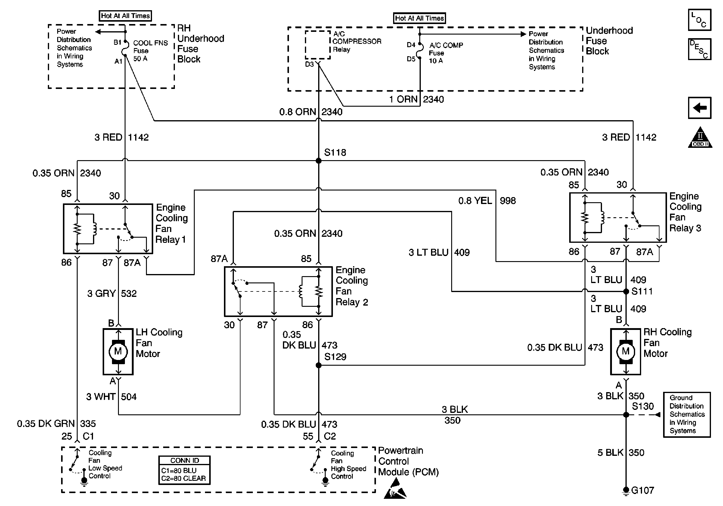
Refer to Engine Controls Schematics
Cooling Fans and Relays

.
Circuit Description
The powertrain control module (PCM) uses output driver modules (ODMs) to control many functions of the engine, and the transaxle. The ODMs supply the ground path for the PCM controlled device when the PCM commands the device ON. Each ODM is able to control several outputs. Unlike the quad driver modules (QDMs) used in earlier model years, the ODMs are able to diagnose each output circuit. The PCM monitors the ODMs for circuit conditions that are incorrect for the commanded state of the ODM. If the PCM detects an improper circuit condition in the ODM that controls the engine cooling fan 1 relay, DTC P0480 will set.
Conditions for Running the DTC
| • | The engine is running. |
| • | System voltage is between 8 and 18 volts. |
| • | Engine speed is greater than 425 RPM. |
Conditions for Setting the DTC
| • | The PCM detects an improper voltage level on the output circuit that controls the engine cooling fan 1 relay. |
| • | The condition exists for at least 10 seconds. |
Action Taken When the DTC Sets
| • | The PCM illuminates the malfunction indicator lamp (MIL) during the second consecutive trip in which the diagnostic test runs and fails. |
| • | The PCM stores the conditions present when the DTC set as Freeze Frame/Failure Records data. |
Conditions for Clearing the MIL/DTC
| • | The PCM will turn the MIL OFF after the third consecutive trip in which the diagnostic runs and passes. |
| • | The history DTC will clear after 40 consecutive warm-up cycles have occurred without a malfunction. |
| • | The DTC can be cleared by using the scan tool Clear DTC Information function. |
Diagnostic Aids
To determine whether an improper voltage level exists on the output circuit, the PCM compares the voltage level to the commanded state. For example, a failure condition exists if the PCM detects a low voltage level when the device is commanded OFF, or a high voltage level when the device is commanded ON.
If the condition is intermittent, refer to Intermittent Conditions in Symptoms.
Step | Action | Value(s) | Yes | No | ||||||
|---|---|---|---|---|---|---|---|---|---|---|
1 | Did you perform the Powertrain On Board Diagnostic (OBD) System Check? | -- | ||||||||
2 | Turn OFF the ignition. Do the engine cooling fans run continuously? | -- | ||||||||
3 |
Did you find and correct the condition? | -- | ||||||||
4 | Is DTC P0481 also set? | -- | ||||||||
5 | Check the fuse that supplies battery voltage to the cooling fan relays. Is the fuse open? | -- | ||||||||
6 | Locate and repair the shorted component or the short to ground in the battery positive feed circuit to the cooling fan relays. Is the action complete? | -- | -- | |||||||
7 | Locate and repair the open battery positive feed circuit between the fuse and the splice. Is the action complete? | -- | -- | |||||||
8 |
Is the test lamp ON? | -- | ||||||||
9 |
Is the test lamp ON? | -- | ||||||||
10 |
Did you find and correct the condition? | -- | ||||||||
11 | Locate and repair the open battery positive coil feed circuit to engine cooling fan relay 1. Refer to Wiring Repairs in Wiring Systems. Is the action complete? | -- | -- | |||||||
12 |
Did you find and correct the condition? | -- | ||||||||
13 | Replace engine cooling fan relay 1. Is the action complete? | -- | -- | |||||||
14 |
Important: Replacement PCM must be programmed. Replace the PCM. Refer to Powertrain Control Module Replacement/Programming . Is the action complete? | -- | -- | |||||||
15 |
Does the scan tool indicate DTC P0480 passed? | -- | System OK |
