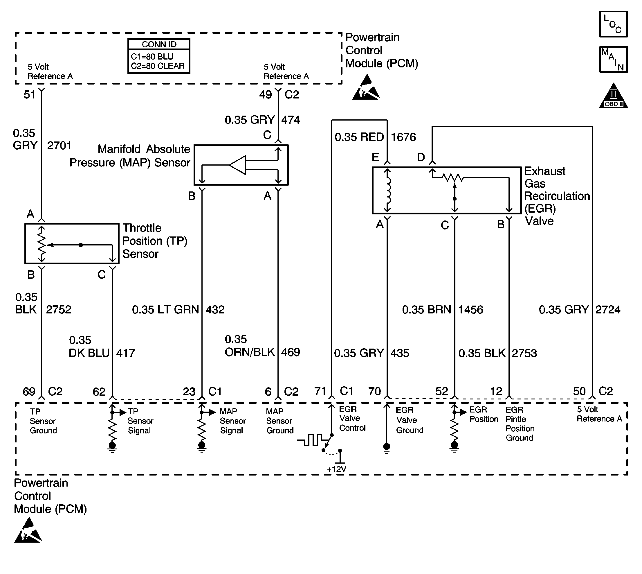
Circuit Description
The PCM uses the 5 Volt Reference A circuit to supply voltage to the following sensors:
| • | Throttle position (TP) sensor |
| • | Manifold absolute pressure (MAP) sensor |
| • | Exhaust gas recirculation (EGR) pintle position sensor |
The PCM monitors the voltage on the 5 Volt Reference A circuit. If the voltage is outside an acceptable range, DTC P1635 will set.
Conditions for Running the DTC
The ignition switch is in the RUN position.
Conditions for Setting the DTC
| • | The PCM detects a voltage out of range condition on the 5 Volt Reference A circuit. |
| • | The condition exists for less than 1 second. |
Action Taken When the DTC Sets
| • | The PCM illuminates the malfunction indicator lamp (MIL) during the second consecutive trip in which the diagnostic test runs and fails. |
| • | The PCM stores the conditions present when the DTC set as Freeze Frame and Fail Records data. |
Conditions for Clearing the MIL/DTC
| • | The PCM will turn the MIL OFF after the third consecutive trip in which the diagnostic runs and passes. |
| • | The history DTC will clear after 40 consecutive warm-up cycles have occurred without a malfunction. |
| • | The DTC can be cleared by using the scan tool Clear DTC Information function. |
Diagnostic Aids
If the condition is intermittent, refer to Intermittent Conditions in Symptoms.
Step | Action | Value(s) | Yes | No |
|---|---|---|---|---|
1 | Did you perform the Powertrain On Board Diagnostic (OBD) System Check? | -- | ||
2 |
Important: Visually/physically inspect the PCM and engine grounds. Ensure that the grounds are clean and secure. If a problem is found, repair as necessary. Refer to Wiring Repairs in Wiring Systems. Observe the 5 Volt Reference display on the scan tool. Does the 5 Volt Reference display OK? | -- | ||
3 |
Does the scan tool indicate that DTC P1635 failed last test? | -- | Go to Diagnostic Aids | |
4 |
Does the 5 Volt Reference display OK? | -- | ||
5 | Observe the MAP sensor display on the scan tool. Does the MAP sensor indicate a voltage near the specified value? | 0V | ||
6 | Test the MAP signal circuit for a short to voltage. Refer to Circuit Testing and Wiring Repairs in Wiring Systems. Did you find and correct the condition? | -- | ||
7 |
Does the 5 Volt Reference display OK? | -- | ||
8 | Observe the TP sensor display on the scan tool. Does the TP sensor indicate a voltage near the specified value? | 0V | ||
9 | Test the TP signal circuit for a short to voltage. Refer to Circuit Testing and Wiring Repairs in Wiring Systems. Did you find and correct the condition? | -- | ||
10 |
Does the 5 Volt Reference display OK? | -- | ||
11 | Observe the Actual EGR Position display on the scan tool. Does the Actual EGR position near the specified value? | 0% | ||
12 | Test the EGR pintle position circuit for a short to voltage. Refer to Circuit Testing and Wiring Repairs in Wiring Systems. Did you find and correct the condition? | -- | ||
13 |
Does the DMM indicate a voltage near the specified value? | 0V | ||
14 |
Did you find and correct the condition? | -- | ||
15 |
Did you find and correct the condition? | -- | ||
16 | Replace the MAP sensor. Refer to Manifold Absolute Pressure Sensor Replacement . Is the action complete? | 5V | -- | |
17 | Replace the TP sensor. Refer to Throttle Position Sensor Replacement . Is the action complete? | -- | -- | |
18 | Replace the EGR valve. Refer to Exhaust Gas Recirculation Valve Replacement . Is the action complete? | B+ | -- | |
19 |
Important: The replacement PCM must be reprogrammed. Replace the PCM. Refer to Powertrain Control Module Replacement/Programming . Is the action complete? | -- | -- | |
20 |
Does the scan tool indicate that DTC P1635 passed? | -- | System OK |
