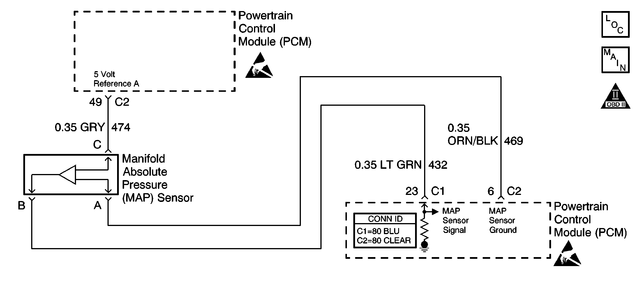
Circuit Description
The manifold absolute pressure (MAP) sensor responds to changes in intake manifold pressure. The PCM supplies a 5 volt reference and a ground for the MAP sensor. The MAP sensor provides a signal to the PCM relative to the pressure changes in the manifold. With low manifold absolute pressure (high vacuum such as during idle or deceleration), the PCM should detect a low MAP sensor signal voltage. With high manifold absolute pressure (low vacuum such as key ON, engine OFF or wide-open throttle), the PCM should detect a high MAP sensor signal voltage. The PCM tests the MAP sensor to ensure that the sensor is functioning properly. The PCM predicts a MAP sensor value based on throttle position and engine speed. The PCM then compares the predicted value to the actual MAP sensor input. DTC P0106 will set if the actual MAP sensor input does not closely match the predicted value.
Conditions for Running the DTC
| • | No TP sensor DTCs are set. |
| • | Engine speed is steady between 1000-4000 RPM. |
| • | Throttle angle is steady. |
| • | Idle air control valve is steady. |
| • | The A/C compressor clutch is steady. |
| • | The torque converter clutch is steady. |
| • | EGR is steady. |
| • | The vehicle brakes are not applied. |
Conditions for Setting the DTC
The actual MAP sensor value does not closely match the predicted value.
The condition is present for 5 seconds.
Action Taken When the DTC Sets
| • | The PCM illuminates the malfunction indicator lamp (MIL) during the second consecutive trip in which the diagnostic test runs and fails. |
| • | The PCM stores the conditions present when the DTC set as Freeze Frame/Failure Records data. |
Conditions for Clearing the MIL/DTC
| • | The PCM will turn the MIL OFF after the third consecutive trip in which the diagnostic runs and passes. |
| • | The history DTC will clear after 40 consecutive warm-up cycles have occurred without a malfunction. |
| • | The DTC can be cleared by using the scan tool Clear DTC Information function. |
Diagnostic Aids
For intermittent conditions, refer Intermittent Conditions in Symptoms.
Test Description
The numbers below refer to the step numbers on the diagnostic table:
-
A throttle position sensor that is stuck in range can cause this DTC to set. Monitor the scan tool while slowly depressing the accelerator pedal.
-
This step tests for a voltage on the throttle position sensor signal circuit.
-
If the scan tool displays 5 volts, the PCM and circuits are OK.
-
A resistance in the throttle position sensor ground circuit can cause this DTC to set. Ensure that the ignition is ON, while performing this test.
-
This step tests for a voltage on the MAP sensor signal circuit.
-
If the scan tool displays 5 volts, the PCM and circuits are OK.
-
This step test the MAP sensors ability to respond to a vacuum. The sensor value should change smoothly as the vacuum increases.
Step | Action | Values | Yes | No | ||||||||
|---|---|---|---|---|---|---|---|---|---|---|---|---|
1 | Did you perform the Powertrain On Board Diagnostic (OBD) System Check? | -- | ||||||||||
Does the TP sensor voltage go from below the specified value to above the specified value? | Below 1.0V to above 4.0V | |||||||||||
Is the TP sensor voltage near the specified value? | 0V | |||||||||||
Jumper the TP sensor 5 volt reference circuit to the TP sensor signal circuit with a fused jumper wire. Is the TP sensor voltage near the specified value? | 5V | |||||||||||
Test the continuity of the TP sensor ground circuit with a DMM to battery ground. Is the resistance below the specified value? | 5 ohms | |||||||||||
6 |
Did you find and correct the condition? | -- | ||||||||||
7 |
Did you find and correct the condition? | -- | ||||||||||
Is the MAP sensor voltage near the specified value? | 0V | |||||||||||
Is the MAP sensor voltage near the specified value? | 5V | |||||||||||
10 | Test the continuity of the MAP sensor ground circuit with a DMM to battery ground. Is the resistance below the specified value? | 5 ohms | ||||||||||
11 |
Did you find and correct the condition? | -- | ||||||||||
12 |
Did you find and correct the condition? | -- | ||||||||||
Important: Each 1 inch of vacuum applied should result in a 3-4 kPa drop in MAP sensor reading. Does the MAP sensor value change smoothly as the vacuum is applied? | 4.5-5V | |||||||||||
14 | With 20 inches of vacuum applied to the MAP sensor, does the scan tool indicate a MAP sensor voltage within the specified range? | 1-2V | ||||||||||
15 |
Does the scan tool indicate a MAP sensor voltage within the specified value? | 4.5-5V | Go to Diagnostic Aids | |||||||||
16 | Replace the TP sensor. Refer to Throttle Position Sensor Replacement . Is the action complete? | -- | -- | |||||||||
17 | Replace the MAP sensor. Refer to Manifold Absolute Pressure Sensor Replacement . Is the action complete? | -- | -- | |||||||||
18 |
Important: Program the replacement PCM. Refer to Powertrain Control Module Replacement/Programming . Replace the PCM. Is the action complete? | -- | -- | |||||||||
19 |
Does the scan tool indicate that DTC P0106 passed? | -- | System OK |
