Tools Required
J 34730-1A Fuel Pressure Gauge
Removal Procedure
- Relieve the fuel system pressure. Refer to Fuel Pressure Relief .
- Raise the vehicle and suitably support. Refer to Lifting and Jacking the Vehicle in General Information.
- Drain the fuel tank. Refer to Fuel Tank Draining .
- Disconnect the fuel feed pipe (1) at the in-line fuel filter and return pipe (2) near the in-line fuel filter.
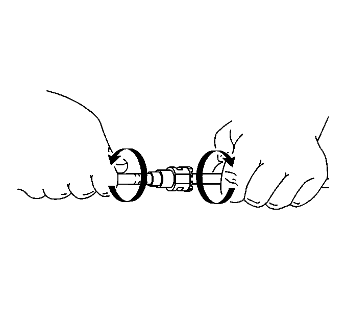
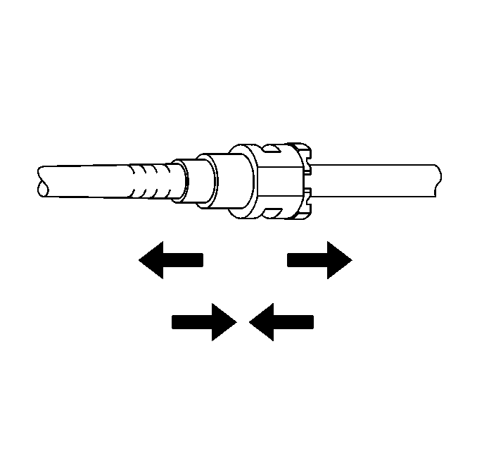
- Grasp both ends of the fuel feed pipe connection and twist ¼ turn in each direction to loosen any dirt in quick connect fittings.
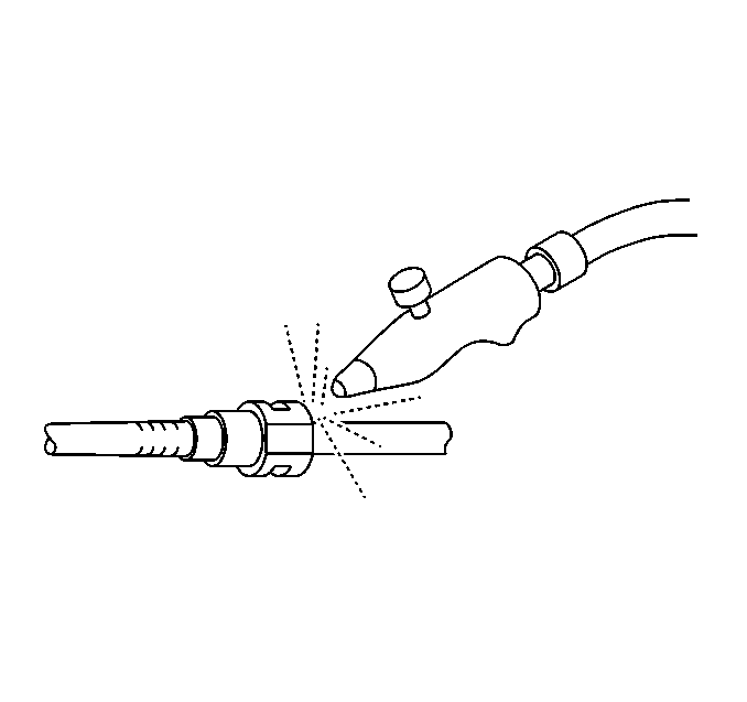
- Blow out dirt from quick connect fittings, using compressed air.
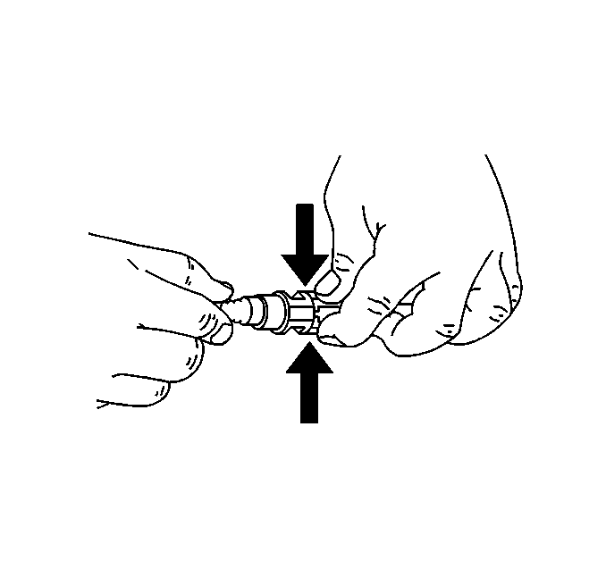
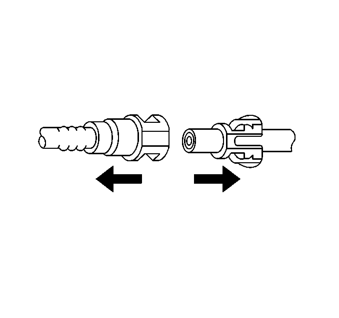
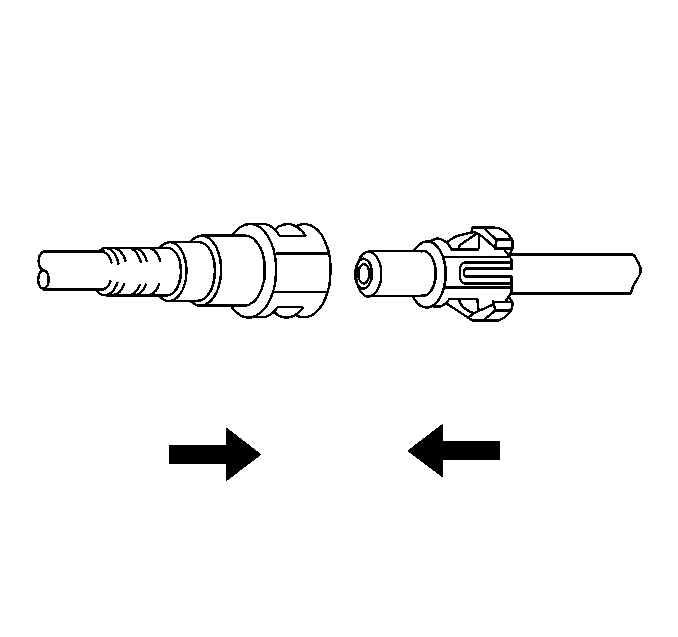
- Squeeze the plastic tabs of male end connector of fuel filter.
- Pull connection apart.
- Repeat steps 5 through 8 for the other fitting.
- Remove the bolt (2) at the fuel filler neck (1).
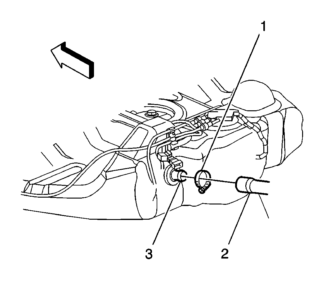
- Loosen the fuel filler neck clamp (1) from the fuel tank filler extension pipe (2).
- Remove the fuel tank fuel tank filler pipe (2) from the fuel tank fuel tank filler extension pipe (3).
- Disconnect the fuel sender (1) electrical connector.
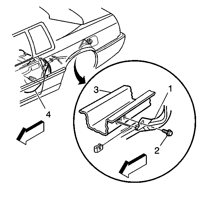
- Remove the exhaust heat shield screws and reposition shield.
- Support the fuel tank and remove the fuel tank retaining strap bolts (2) from the fuel tank retaining strap (3).
- Lower the fuel tank and disconnect the EVAP pipe(s).
- Inspect the electrical connectors for dirt and damage. Clean or replace as required.
- Remove the fuel sender assembly (1) from the fuel tank. Refer to Fuel Sender Assembly Replacement .
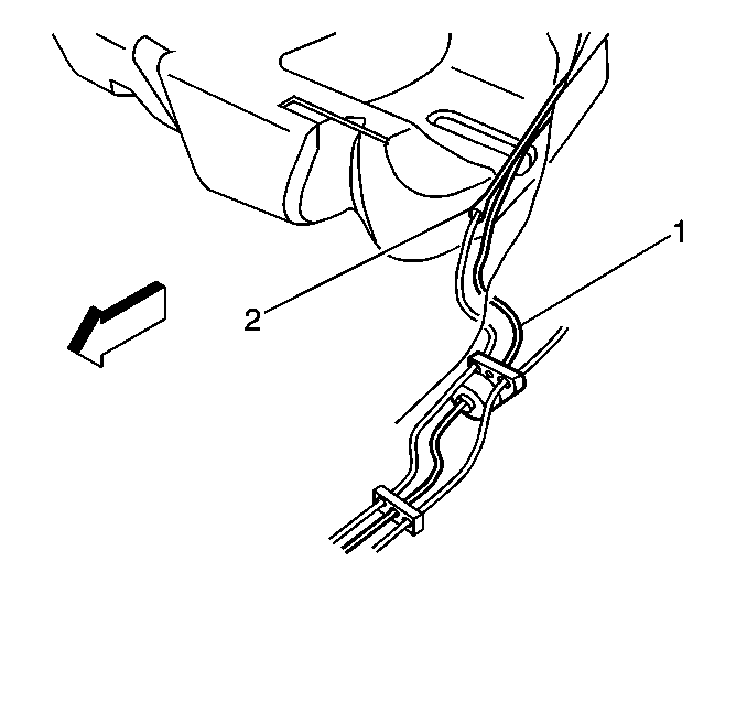
Important: If nylon fuel feed or return pipes become kinked, and cannot be straightened, they must be replaced.
Caution: Wear safety glasses when using compressed air in order to prevent eye injury.

Notice: Do not bend the fuel tank straps as this may damage the straps.
Installation Procedure
- Lightly lubricate the inside diameter of the lip seal with clean engine oil.
- Install fuel sender assembly (1) into the fuel tank (4). Refer to Fuel Sender Assembly Replacement .
- Install fuel tank retaining straps (3) attaching bolts (2) with the aid of an assistant to the fuel tank (2).
- Raise the fuel tank and connect EVAP pipe(s).
- Install exhaust heat shield screws.
- Connect the fuel sender electrical connector.
- Install the fuel filler neck clamp (1) to the fuel tank filler extension pipe (2).
- Install the fuel tank fuel tank filler pipe (2) to the fuel tank fuel tank filler extension pipe (3).
- Install the bolt (2) to the fuel filler neck (1).
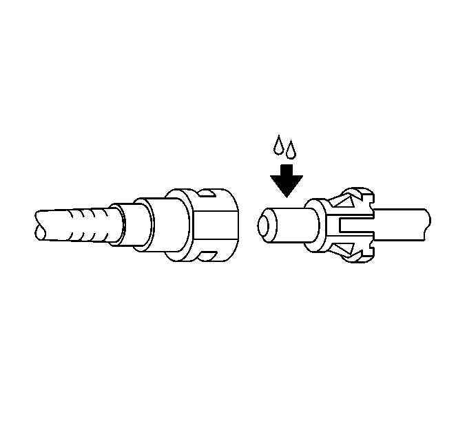
- Apply a few drops of clean engine oil to the male connector pipe ends.
- Push connectors together to cause the retaining tabs/fingers to snap into place.
- Pull on both ends of each connection to make sure connection is secure, once installed.
- Lower the vehicle.
- Install the fuel filler cap.
- Add fuel to the fuel tank.
- Connect the negative battery cable. Refer to Battery Negative Cable Disconnection and Connection in Engine Electrical.
- Inspect for fuel leaks.
- Install the fuel injector sight shield (1) to the engine.
- Install the fuel injector sight shield nuts (2).

Important: Always install a new lip seal when servicing the modular fuel sender assembly.
Important: Assure proper location of fuel sender pipes.
Notice: Use the correct fastener in the correct location. Replacement fasteners must be the correct part number for that application. Fasteners requiring replacement or fasteners requiring the use of thread locking compound or sealant are identified in the service procedure. Do not use paints, lubricants, or corrosion inhibitors on fasteners or fastener joint surfaces unless specified. These coatings affect fastener torque and joint clamping force and may damage the fastener. Use the correct tightening sequence and specifications when installing fasteners in order to avoid damage to parts and systems.
Tighten
Tighten the fuel tank strap bolts to 46 N·m (34 lb ft).

Tighten
Tighten the clamps to 2.5 N·m (22 lb in).

Caution: Always apply a few drops of clean engine oil to the male pipe ends before connecting the fuel pipe fittings in order to reduce the risk of fire and personal injury. This will ensure proper reconnection and prevent a possible fuel leak. During normal operation, the O-rings located in the female connector will swell and may prevent proper reconnection if not lubricated.

Caution: Unless directed otherwise, the ignition and start switch must be in the OFF or LOCK position, and all electrical loads must be OFF before servicing any electrical component. Disconnect the negative battery cable to prevent an electrical spark should a tool or equipment come in contact with an exposed electrical terminal. Failure to follow these precautions may result in personal injury and/or damage to the vehicle or its components.
| 17.1. | Turn ON the ignition to for 2 seconds. |
| 17.2. | Turn OFF the ignition to for 10 seconds. |
| 17.3. | Turn ON the ignition. |
| 17.4. | Check for fuel leaks. |

Tighten
Tighten the nuts 3 N·m (27 lb in).
