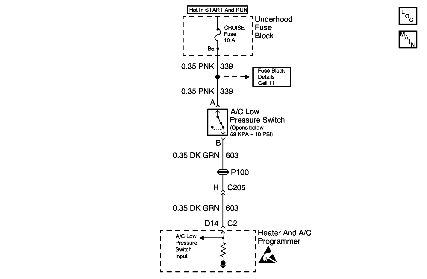
Circuit Description
In the process of controlling the compressor clutch, the heater and A/C programmer monitors certain inputs for an indication of a low refrigerant charge. If the system refrigerant state of charge falls below approximately 1/4 capacity, the heater and A/C programmer is capable of detecting this condition. The programmer will display VERY LOW REFRIGERANT--A/C COMPRESSOR OFF on the driver information center (DIC) in order to warn the operator.
The heater and A/C programmer determines the state of the charge by monitoring the temperature change in the low temperature sensor during the compressor engagement. This temperature drop is referenced by the heater and A/C programmer as a function of the ambient air temperature. If the refrigerant charge is too low, the refrigerant boils instantaneously after passing through the orifice tube. This action creates a large rapid change in the low temperature sensor reading. After several incidents are counted, the heater and A/C programmer sets DTC B1347. The message VERY LOW REFRIGERANT--A/C COMPRESSOR OFF will be displayed on the DIC. If a DTC B1347 is set, the compressor clutch disengages and remains disengaged until DTC B1347 is cleared. DTC B1347 may repeat if excessive pressure exists in the A/C charging station tank. Repair the A/C charging station before properly diagnosing DTC B1347.
Failure Conditions
The low side refrigerant temperature drops too quickly during several of the compressor cycles.
Action Taken When the DTC Sets
| • | The system disables the A/C compressor until the DTC is cleared. |
| • | The system displays the VERY LOW REFRIGERANT--A/C COMPRESSOR OFF message on the DIC. |
Test Description
-
Perform the Diagnostic System Check before continuing with the diagnosis of this DTC.
-
This test inspects for an intermittent open or short in the pressure switch circuit.
-
This test inspects for restrictions in the refrigerant system.
Step | Action | Value(s) | Yes | No |
|---|---|---|---|---|
Did you perform the diagnostic system check? | -- | Go to Step 2 | Go to Diagnostic System Check | |
Does the display remain ON? | -- | Go to Step 4 | Go to Step 3 | |
Do the calculated and gauge pressures agree within the specified value? | 10% | Go to Step 5 | Go to Step 6 | |
4 |
Is the repair complete? | -- | Go to Step 7 | -- |
5 |
Is the repair complete? | -- | Go to Step 7 | -- |
6 | Inspect for a restriction within the refrigerant system between the temperature sensor and the service connection gauge that did not agree. Is the repair complete? | -- | Go to Step 7 | -- |
7 | Using the Scan Tool clear the DTC and verify the operation. Is the repair complete? | -- | Go to Diagnostic System Check | -- |
