This section provides an overview of the instrument cluster
(IPC) operation. The following sections may provide additional information
that may assist in the diagnosis of an IPC malfunction:
| • | For wiring schematics, refer to Audible Warning Schematics. |
| • | For component locations, refer to Audible Warnings Components. |
| • | For Class 2 communications diagnosis, refer to Body Control
System Diagnostic System Check in Body Control System. |
| • | For the vehicle diagnostic system, refer to Body Control System
Diagnostic System Check in Body Control System. |
| • | For the IPC removal procedure, refer to Instrument Panel Replacement. |
Instrument Cluster (IPC) Overview
The IPC serves as the primary vehicle interface for the driver. The
IPC used in the vehicle consists of a digital IPC or an analog IPC. Both IPC
versions contain similar functions. These functions permit the driver to
monitor the operation and/or to control the various vehicle systems.
Both of the IPCs have the capability in order to detect various malfunctions
in the following components:
| • | The components and systems with which the IPC communicates |
When the IPC (or another microprocessor-controlled module) detects a
malfunction, one of the following actions may occur:
| • | An IPC indicator is activated. |
| • | A message is displayed on the driver message center. |
| • | A DTC is set in the IPC (or another module's) memory. |
Some DTCs may not cause an IPC message to be displayed or activate an
IPC indicator lamp.
The IPC indicators and messages are activated in order to alert the
driver that a system malfunction was detected.
The DTCs are activated in order to ensure that a qualified technician
may identify and diagnose a system malfunction.
This vehicle allows the technician to display various input and output
parameters and to any set DTCs using one of the following methods:
- Enter the vehicle diagnostic system. Display the information on
the IPC driver message center. Refer to Vehicle Diagnostic System.
- Connect a Scan Tool
to the DLC.
The Scan Tool
is
the preferred tool for IPC diagnosis.
The IPC communicates with the following modules over the Class 2
serial data line:
| • | The body control module (PZM) |
| • | The cellular telephone module (PHN) |
| • | The climate control panel (CCP) |
| • | The data link connector (DLC) |
| • | The electronic brake and traction control module (EBTCM) |
| • | The heater and A/C programmer (ACM) |
| • | The integrated radio chassis (IRC) |
| • | The inflatable restraint sensing and diagnostic module (SDM) |
| • | The memory mirror module (MMM) |
| • | The memory seat module (MSM) |
| • | The powertrain control module (PCM) |
| • | The road sensing suspension (RSS) (optional) |
Important: The following microprocessors may not be serviced separately:
| • | The electrically erasable programmable read only memory (EEPROM)
microprocessor that saves critical data even when the battery power is removed.
This microprocessor stores the following settings: |
| • | The manufacturing information |
| • | The vehicle identification number (VIN) |
| • | The flash EPROM microprocessor that contains a software program
used by the IPC in order to monitor, control, and display the various vehicle
parameters. The EPROM retains all of the program data if the battery power
is removed. |
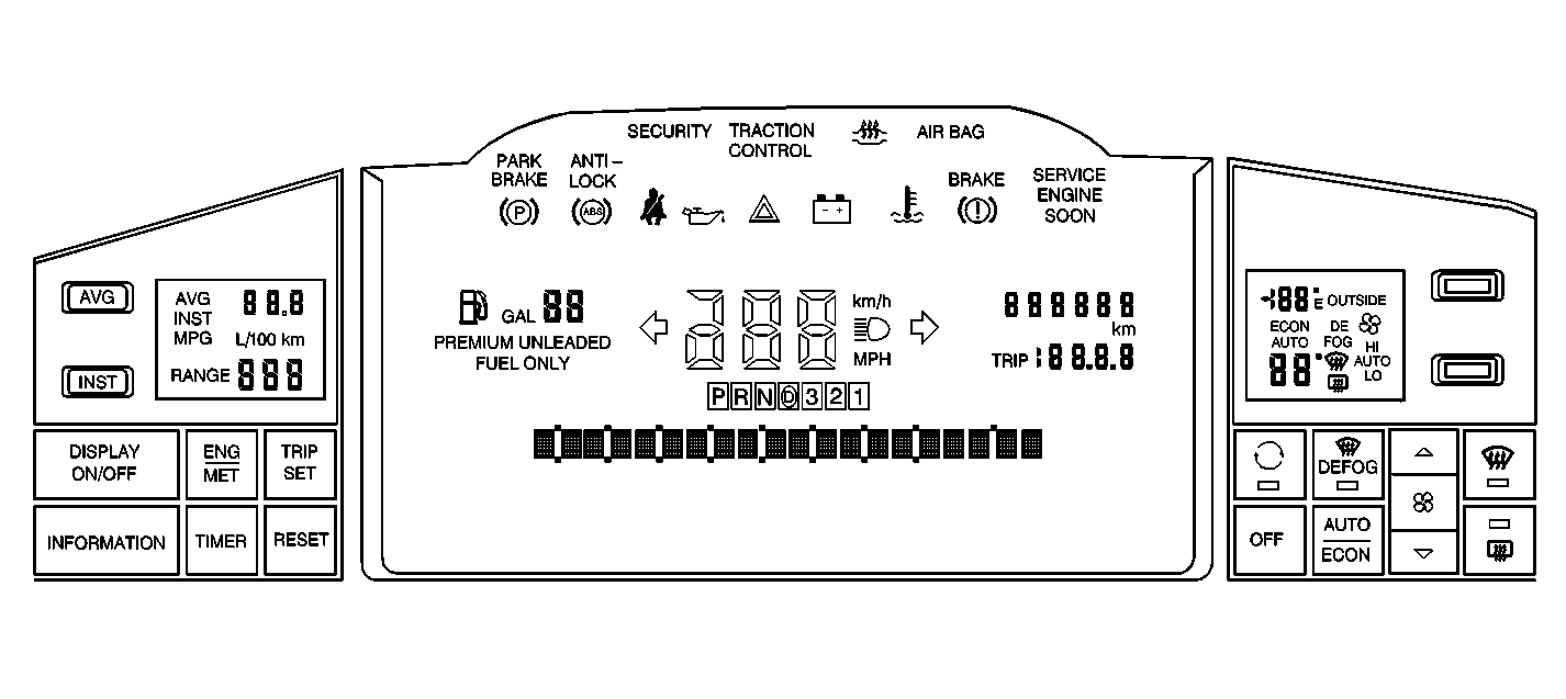
Digital Instrument Cluster

The digital IPC provides
numeric readouts for the following functions:
| • | The vehicle speedometer |
| • | The fuel level center portion of the IPC |
the following components are located within the center portion of the
IPC:
| • | The driver message center |
The driver message center displays various warning and status messages
to the driver and the technician. The following are located on the left side
of the IPC:
| • | The driver information center (DIC) buttons |
The following are located on the right side of the IPC:
| • | The heater and A/C system control buttons |
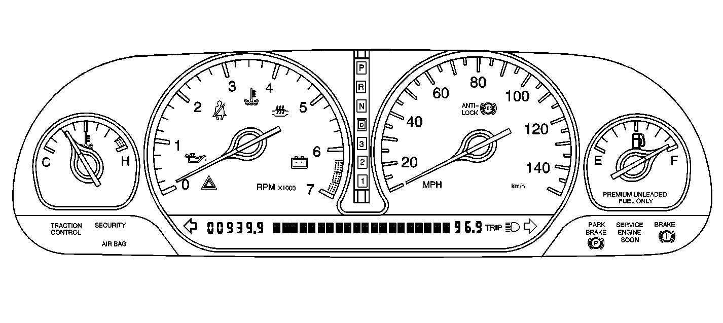
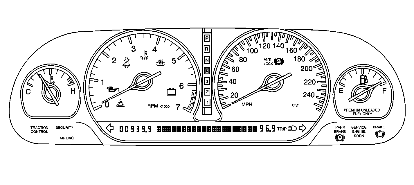
Analog Instrument Cluster
The analog instrument cluster is available in the following 2 models:


The analog gauge package provides swing needle readouts for the following
items:
| • | The coolant temperature |
A driver message center is located within the IPC for displaying various
warning and status messages. Since no button controls are located on the analog
IPC, a separate climate control panel (CCP) is provided for controlling
the heater and A/C system. a separate driver information center that controls
the driver message center. For information and diagnosis of the CCP, refer
to HVAC.


