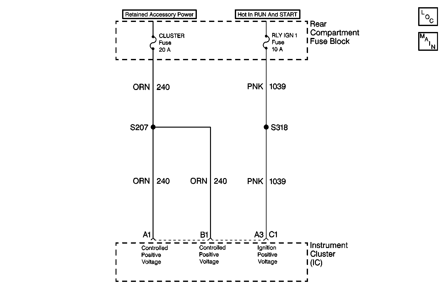
For 1990-2009 cars only

Circuit Description
The battery voltage is supplied to the IPC connector C1 terminals A1 and B1.
When the IPC is awake, the voltage at the IPC connector C1 terminals A1 and B1 are measured every 300 ms.
This DTC indicates a circuit malfunction is preventing the alternator from charging.
Conditions for Setting the DTC
The battery voltage measured at the IPC connector C1 terminals A1 and B1 is more than 15.5 V for 4 monitoring cycles.
Action Taken When the DTC Sets
| • | The IPC displays the BATTERY VOLTAGE HIGH message on the driver message center. |
| • | No loss of the class 2 serial data DTCs are set. |
Diagnostic Aids
The DTC may set if the vehicle is connected to a battery charger set on fast or boost charge.
Step | Action | Value(s) | Yes | No |
|---|---|---|---|---|
1 | Did you perform the Diagnostic System Check? | -- | Go to Step 2 | |
2 |
Is the voltage greater than the specified value? | 15.5 V | Go to the Generator Electrical Test in Engine Electrical | Go to Step 3 |
3 | Replace the IPC. Is the repair complete? | -- | -- |
