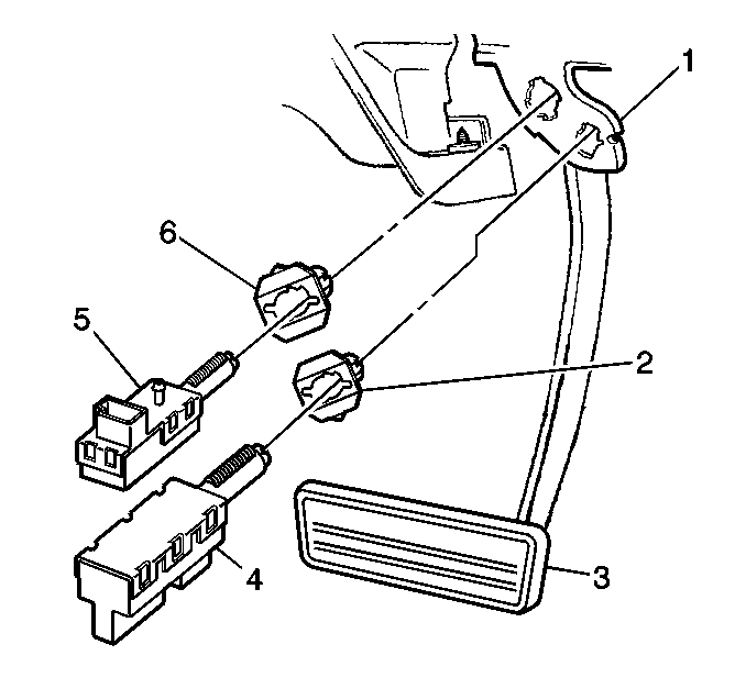
For 1990-2009 cars only

Important: Do not depress the brake pedal (3) during the adjustment procedure.
Notice: Proper stoplamp switch adjustment is essential. Improper stoplamp switch adjustment could cause brake drag and excessive brake lining wear.
Adjust the release switch (5) assembly and the stoplamp switch (4) assembly after you assemble the brake booster pushrod to the brake pedal assembly. Adjust the following components together:
| • | The cruise control release switch (5) |
| • | The stoplamp switch (4) |
Incorrect switch adjustment may cause the cruise control system to function improperly. For additional information about switch replacement, refer to Stop Lamp Switch Replacement in Hydraulic Brakes.
Adjustment Procedure
- Insert the cruise release switch into the retainer until the switch fully seats against the brake pedal arm.
- Twist the switch in order to lock the switch into position.
- Measure the distance from the end of the barrel on the cruise release switch to the pedal arm. Ensure that the clearance is 1.5-1.7 mm (1/16 in). Repeat the previous 2 steps if the measurement is incorrect.
- Measure the travel at the centerline of the brake pedal assembly pad. The following contacts must be closed at 3.5-12.5 mm (1/8-1/2 in) of brake pedal assembly travel:
| • | The release switch assembly (5) |
| • | The stoplamp switch assembly (4) |
| • | The nominal actuation of the stoplamp switch assembly (4) is approximately 4.5 mm (3/16 in). |
