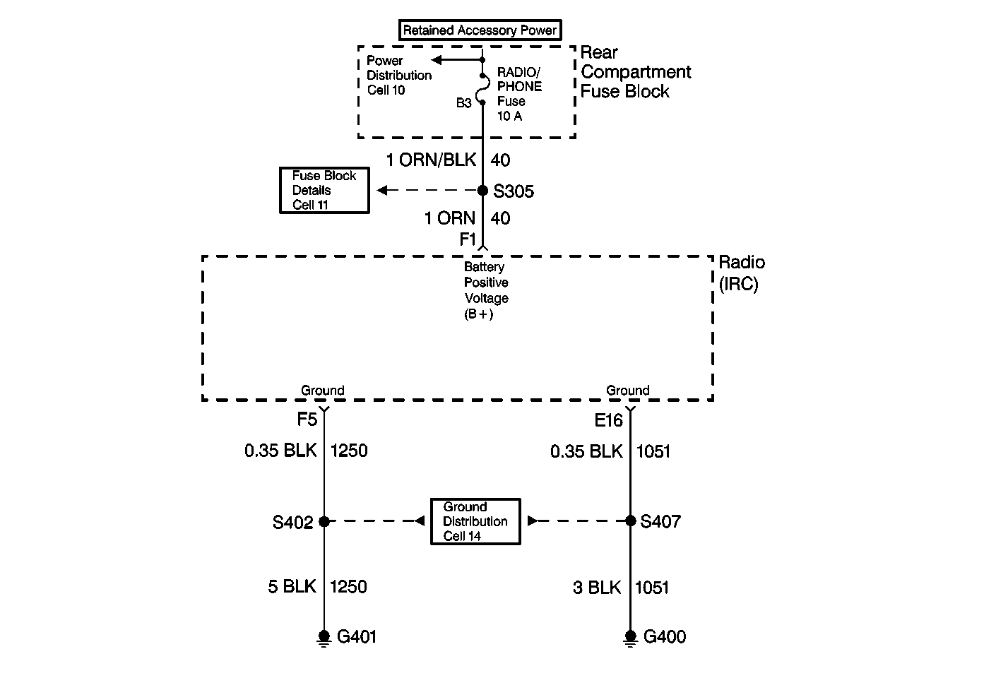
Circuit Description
The battery voltage is supplied to the radio (IRC) at terminal F1. The radio (IRC) uses this power feed in order to perform all of the radio's functions. The radio (IRC) measures the battery voltage at terminal F1 every 300 ms.
Conditions for Setting the DTC
The battery voltage measured at terminal F1 is more than 15.5 V for 4 consecrative monitoring cycles.
Action Taken When the DTC Sets
When DTC B1982 is current, class 2 loss of serial data communication DTCs will not set.
Conditions for Clearing the MIL/DTC
The battery voltage is less than 15.5 V in the next monitoring cycle.
Diagnostic Aids
DTC B1982 may set if the vehicle is connected to a battery charger set on FAST or BOOST charge.
Step | Action | Value(s) | Yes | No |
|---|---|---|---|---|
1 | Did you perform the Radio/Audio System Diagnostic System Check? | -- | Go to Step 2 | |
2 |
Does the scan tool indicate that the voltage is above 15.5 V? | -- | Go to Charging System Check in Engine Electrical | Go to Step 3 |
3 | Replace the radio. Refer to one of the flowing: Is the repair complete? | -- | -- |
