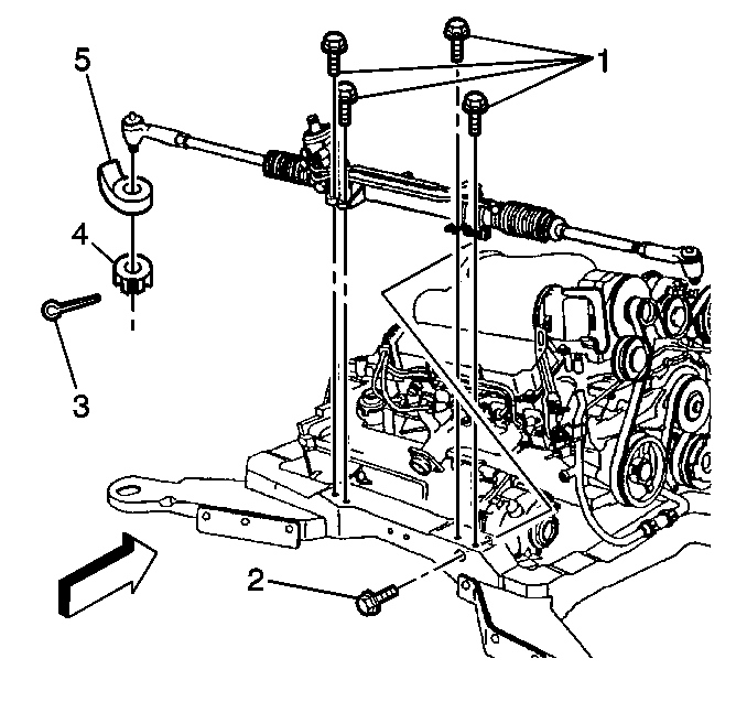
Removal Procedure
- Remove the intermediate shaft lower coupling.
- Raise and support the vehicle. Refer to Lifting and Jacking the Vehicle in General Information.
- Remove the left front tire and wheel assembly. Refer to Tire Mounting and Dismounting in Tire and Wheels.
- Remove the road sensing suspension position sensor.
- Remove the road sensing suspension links.
- Remove both tie rod ends from the steering knuckles (5).
- Remove the exhaust Y pipe
- Support the rear of the frame using a screw jack.
- Loosen the number 2 and number 3 body mount bolts.
- Remove the heat shield.
- Remove the plastic line retainer.
- Disconnect the pressure and return pipes from the gear. Refer to Power Steering Hoses Replacement .
- Disconnect the Magnasteer™ electrical connector.
- Remove the 5 rack and pinion attaching bolts (1,2).
- Remove the rack and pinion assembly. Slide the assembly out to one side.
- Remove the boots and inner tie rod assemblies.

Slowly lower the rear of the frame.
Installation Procedure
- Install the inner tie rod and boot assemblies.
- Install the rack and pinion assembly.
- Install the 5 rack and pinion attaching bolts (1,2).
- Connect the Magnasteer™ electrical connector.
- Connect the pressure and return pipes to the gear.
- Install the plastic line retainer.
- Install the heat shield.
- Raise the frame. Tighten the body mount bolts.
- Install the exhaust Y pipe at the converter.
- Install the tie rod ends.
- Tighten the nut an additional 1/3 turn (2 flats).
- Install the road sensing suspension position sensor.
- Install the tire and wheel assemblies.
- Lower the vehicle.
- Install the intermediate shaft lower coupling. Refer to Intermediate Steering Shaft in Steering Wheel and Column.
- Fill the power steering system. Refer to Draining the Power Steering System .
- Bleed the power steering system. Refer to .

Notice: Use the correct fastener in the correct location. Replacement fasteners must be the correct part number for that application. Fasteners requiring replacement or fasteners requiring the use of thread locking compound or sealant are identified in the service procedure. Do not use paints, lubricants, or corrosion inhibitors on fasteners or fastener joint surfaces unless specified. These coatings affect fastener torque and joint clamping force and may damage the fastener. Use the correct tightening sequence and specifications when installing fasteners in order to avoid damage to parts and systems.
Tighten
Tighten the bolts to 68 N·m (50 lb ft).
Tighten
Tighten the pressure and return pipes at the gear to 27 N·m
(20 lb ft).
Important: When tightening the tie rod end nut, a minimum torque of 45 N·m (33 lb ft) must be obtained. If 45 N·m (33 lb ft) is not obtained, inspect the nut for stripped threads. If the threads are satisfactory, replace the tie rod end and knuckle. After tightening the castellated nut to specification, align the slot in the nut to the cotter pin (3) hole by tightening only. DO NOT loosen the nut for the cotter pin (3) installation.
Tighten
Tighten the tie rod end nut to 10 N·m (7.5 lb ft).
Tighten
Tighten the intermediate shaft coupling bolt to 47 N·m
(35 lb ft).
