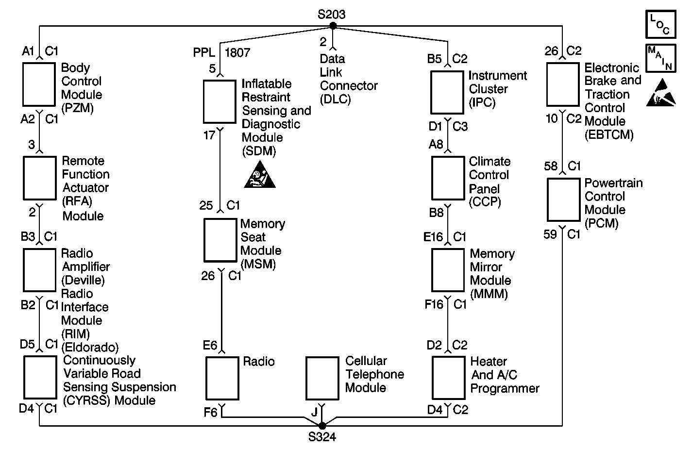
Circuit Description
The class 2 serial data line communicates information between the modules. Each module connected to the serial data line is assigned a recognition code, or address. This code is used in order to identify which modules are communicating. Modules communicate with each other by periodically sending state of health (SOH) messages. When the ignition switch is in RUN, each module that is communicating on the serial data line sends an SOH message every 2 seconds. This ensures that the system is operating properly. The module also monitors the serial data line for short to voltage. If the module detects a short to voltage for more than 3.0 seconds, the module stores the class 2 bus shorted to voltage DTC U1301.
Conditions for Setting the DTC
The module detects that the class 2 serial data line is shorted to battery for at least 3.0 seconds.
Action Taken When the DTC Sets
| • | DTC U1301 is stored in the module. |
| • | The module uses the default values for any information needed from the other modules on the class 2 serial data line. |
| • | This DTC does not cause a driver warning message to appear. |
Conditions for Clearing the DTC
| • | This DTC clears (status changes from current to history) when the module detects the class 2 bus is not shorted to battery. |
| • | A history DTC clears after 50 consecutive ignition cycles if the conditions for setting the DTC are no longer present. |
| • | Current and history DTCs may be cleared manually by using a scan tool. |
Diagnostic Aids
This DTC is not received as current because the class 2 serial data line does not function during this condition.
Step | Action | Value(s) | Yes | No |
|---|---|---|---|---|
1 | Did you perform the Data Link Communications Diagnostic System Check? | -- | Go to Step 2 | |
2 | Attempt to establish communication with all of the modules using a scan tool. Does the scan tool communicate with all of the modules? | -- | Go to Step 3 | Go to the appropriate diagnostic system check for the module that is not communicating |
3 | Repair the intermittent short to battery positive voltage (B+) in the class 2 serial data line CKT 1807 (PPL). Did you complete the repair? | -- | Go to Step 4 | -- |
4 |
Are all of the DTCs cleared? | -- | -- |
