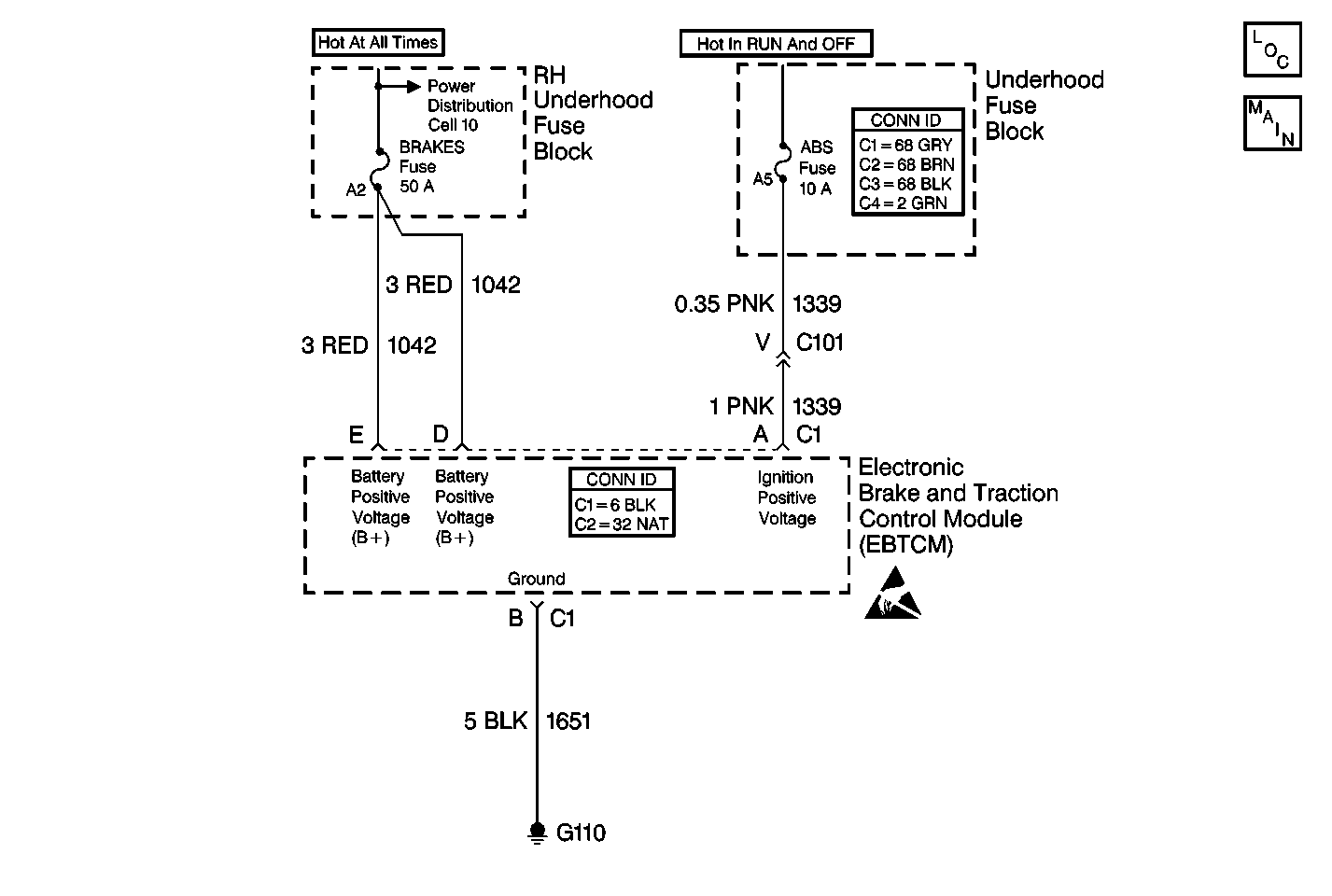
Circuit Description
This circuit is used to monitor the voltage level available to the EBTCM. If the voltage drops below 10.5 volts, full performance of the ABS/TCS/Stabilitrak® is not guaranteed. During ABS/TCS/Stabilitrak® operation, several current requirements will cause a drop in battery voltage. Prior to ABS/TCS/Stabilitrak® operation, the circuit monitors voltage in order to indicate a good charging system condition. The circuit also monitors the voltage during ABS/TCS/Stabiltrak® operation, when the voltage may drop significantly
Conditions for Setting the DTC
All of the following conditions occur:
| • | The vehicle speed is greater than 8 km/h (5 mph). |
| • | The battery positive voltage (B+) is less than 10.5 volts. |
| • | The ignition voltage is less than 10.5 volts. |
Action Taken When the DTC Sets
| • | A malfunction DTC is stored. |
| • | The ABS/TCS/Stabilitrak® is disabled. |
| • | The ABS indicator is turned ON. |
| • | The TRACTION CONTROL indicator is turned ON. |
| • | The DIC displays the SERVICE STABILITY SYS message. |
Conditions for Clearing the DTC
| • | The condition for DTC is no longer present and you used scan tool Clear DTCs function. |
| • | The condition for DTC is no longer present and you used the On-Board Clear DTCs function. |
| • | The EBTCM does not detect the DTC in 50 drive cycles. |
Diagnostic Aids
| • | Thoroughly inspect the wiring and the connectors. Failure to carefully and fully inspect the wiring and the connectors may result in misdiagnosis. Misdiagnosis may cause part replacement with the reappearance of the malfunction. |
| • | If an intermittent malfunction exists refer to Intermittents and Poor Connections Diagnosis in Wiring Systems. |
| • | Inspect for other low voltage conditions. |
| • | Test the charging system. Refer to Charging System Check in Engine Electrical. |
| • | Possible causes for this DTC include the following conditions: |
| - | A charging system malfunction |
| - | An excessive battery draw |
| - | A weak battery |
| - | A faulty system ground |
Test Description
The numbers below refer to step numbers on the diagnostic table.
Step | Action | Value(s) | Yes | No |
|---|---|---|---|---|
1 | Did you perform the ABS Diagnostic System Check? | -- | Go to Step 2 | |
2 | Inspect the charging system. Refer to Starting System Check in Engine Electrical. Is the charging system OK? | -- | Go to Step 3 | Go to Charging System Check in Engine Electrical |
3 |
Is their evidence of any corrosion or damage? | -- | Go to Step 7 | Go to Step 4 |
Is the resistance less than the specified value? | 2 ohms | Go to Step 5 | Go to Step 8 | |
5 |
Are both voltage measurements greater than the specified value? | 10.5 V | Go to Step 6 | Go to Battery Check in Engine Electrical |
Is the voltage greater than the specified value? | 10.5 V | Go to Step 9 | Go to Battery Check in Engine Electrical | |
7 | Repair as necessary Did you complete the repair? | -- | -- | |
8 | Repair the open or high resistance in CKT 1651. Refer to Wiring Repairs in Wiring Systems. Did you complete the repair? | -- | -- | |
9 | Replace the EBTCM. Refer to Electronic Brake Control Module Replacement . Did you complete the repair? | -- | -- |
