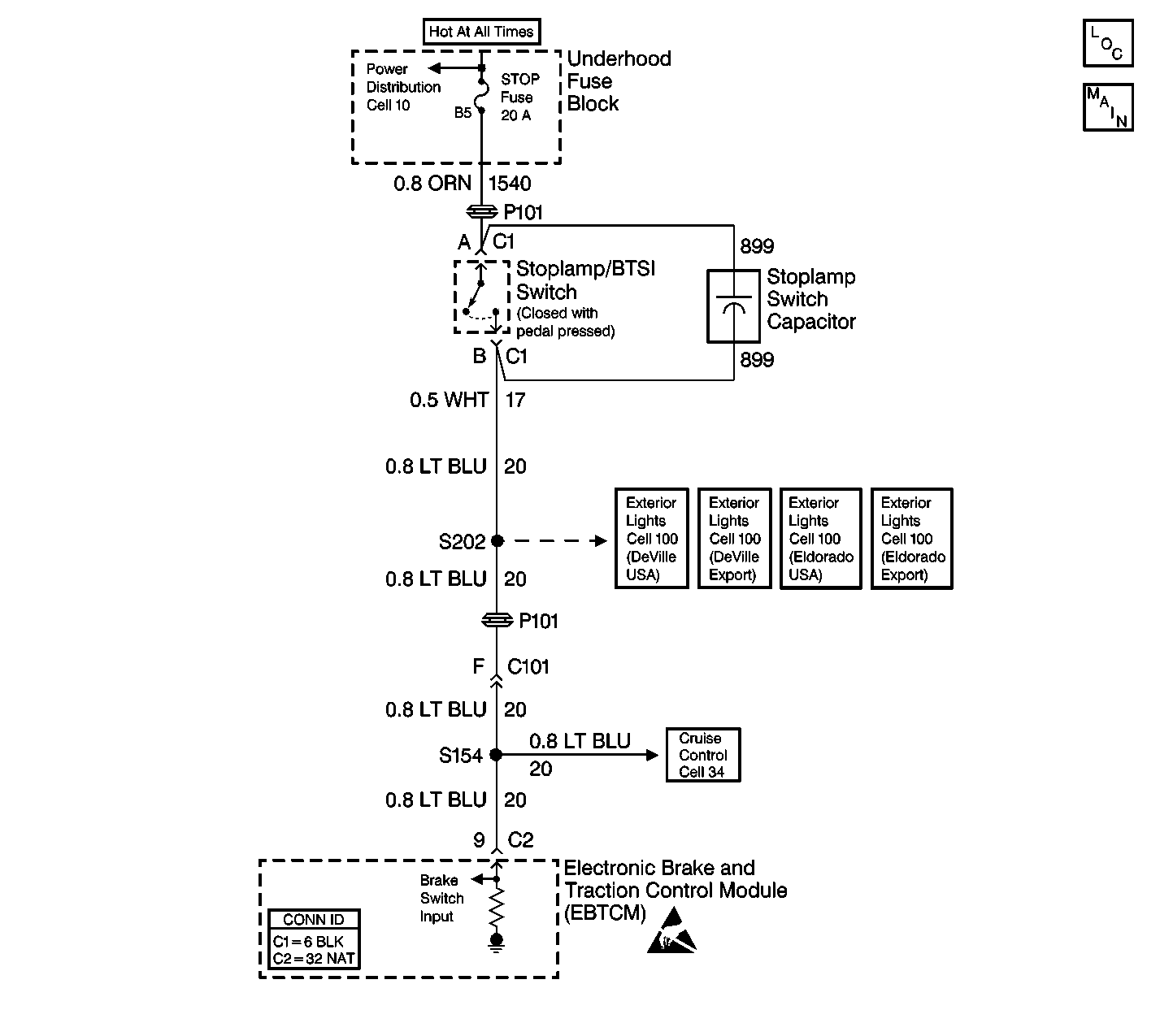
Circuit Description
This circuit detects an open stoplamp/BTSI switch in the non-ABS mode. The EBTCM looks for a deceleration rate that indicates braking action and requires several repeats of this detection method in order to verify this assumption. In each case, the TCS will not be available since the EBTCM detects no stoplamp/BTSI switch voltage.
Conditions for Setting the DTC
The stoplamp switch remains open for 3 deceleration cycles.
Action Taken When the DTC Sets
| • | A malfunction DTC is stored. |
| • | The TCS is disabled. |
| • | The TRACTION CONTROL indicator is turned ON. |
| • | The ABS remains functional. |
Conditions for Clearing the DTC
| • | The condition for DTC is no longer present and you used scan tool Clear DTCs function. |
| • | The condition for DTC is no longer present and you used the On-Board Clear DTCs function. |
| • | The EBTCM does not detect the DTC in 50 drive cycles. |
Diagnostic Aids
| • | If any wheel speed sensor DTCs are present, diagnose them first. Refer to Diagnostic Trouble Code (DTC) List . |
| • | Thoroughly inspect the wiring and the connectors. Failure to carefully and fully inspect the wiring and the connectors may result in misdiagnosis. Misdiagnosis may cause part replacement with the reappearance of the malfunction. |
| • | An intermittent malfunction may be caused by a poor connection, broken insulation, or a wire that is broken inside the insulation. |
| • | If an intermittent malfunction exists, refer to Intermittents and Poor Connections Diagnosis in Wiring Systems. |
| • | This DTC may be caused by one of the following conditions: |
| - | An open stoplamp/BTSI switch |
| - | An open STOP Fuse |
| - | The stoplamp/BTSI switch is misadjusted. |
| - | Erratic wheel speeds |
| - | The circuit has a wiring problem, terminal corrosion, or poor connections. |
Test Description
The numbers below refer to step numbers on the diagnostic table.
-
This step checks if the stoplamp/BTSI switch and the power distribution are functional.
-
This step checks for voltage at the EBTCM.
-
This step checks the stoplamp/BTSI switch.
Step | Action | Value(s) | Yes | No |
|---|---|---|---|---|
1 | Did you perform the ABS Diagnostic System Check? | -- | Go to Step 2 | |
2 | Are any wheel speed sensor DTCs present? | -- | Go to Step 3 | |
Press the brake pedal. Do the brake lights turn on? | -- | Go to Step 4 | Go to Step 7 | |
Is the voltage within the specified range? | Battery Voltage | Go to Step 5 | Go to Step 6 | |
5 | Replace the EBTCM. Refer to Electronic Brake Control Module Replacement . Did you complete the repair? | -- | -- | |
6 | Repair the open in CKT 20. Refer to Wiring Repairs in Wiring Systems. Did you complete the repair? | -- | -- | |
7 | Inspect the underhood fuse block STOP LP Fuse. Is the fuse good? | -- | Go to Step 8 | Go to Step 12 |
8 |
Is the voltage within the specified range? | Battery Voltage | Go to Step 10 | Go to Step 9 |
9 | Repair the open in CKT 1540. Refer to Wiring Repairs in Wiring Systems. Did you complete the repair? | -- | -- | |
Connect a fused jumper wire between the stoplamp/BTSI switch harness connector C1 terminal A and terminal B. Do the brake lamps turn on? | -- | Go to Step 11 | Go to Step 6 | |
11 | Adjust or repair the stoplamp/BTSI switch as necessary. Refer to Stop Lamp Switch Replacement or Stop Lamp Switch Adjustment in Hydraulic Brakes. Did you complete the repair? | -- | -- | |
12 |
Is the fuse good? | -- | Go to Step 14 | Go to Step 13 |
13 | Repair the short to ground in CKT 1540. Refer to Wiring Repairs in Wiring Systems. Did you complete the repair? | -- | -- | |
14 |
Is the fuse good? | -- | Go to Step 15 | |
15 |
Is the fuse good? | -- | Go to Step 5 | Go to Step 16 |
16 | Repair the short to ground in CKT 20. Refer to Wiring Repairs in Wiring Systems. Did you complete the repair? | -- | -- |
