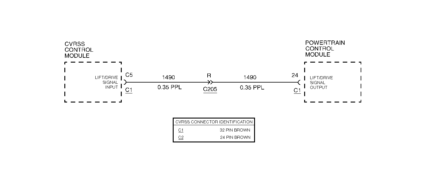
Circuit Description
The CVRSS control module receives a lift/dive signal from the Powertrain Control Module (PCM). Under normal conditions, this signal is 5 volts. The PCM grounds this circuit when the vehicle is accelerating rapidly (LIFT) or braking hard (DIVE). When the lift/dive signal goes low (approximately 0 volts), the CVRSS control module commands all four CVRSS dampers to a FIRM condition.
Conditions for Setting the DTC
The DTC is set when the CVRSS control module does not sense the low-to-high transition on the lift/dive line within 31 seconds after the ignition is turned ON.
The DTC turns HISTORY when the CVRSS control module senses the low-to high transition on the lift/dive signal from the PCM during a valid test period.
Action Taken When the DTC Sets
| • | The CVRSS lift/dive function will be disabled. |
| • | The vehicle will pitch more during a braking or wide open throttle condition. |
| • | The SERVICE RIDE CONTROL message will be displayed. |
Conditions for Clearing the MIL/DTC
| • | Use the scan tool. |
| • | Use the On-Board diagnostic CLEAR RSS CODES feature. |
Diagnostic Aids
As part of the vehicle diagnostic system, the PCM toggles the lift/dive line within 31 seconds after the ignition is turned ON. This allows the CVRSS module to determine if the line is faulted or not. A retry is attempted every four minutes until successful.
An intermittent short circuit to ground or open circuit condition in CKT 1490 may cause a random firm/soft ride condition.
Test Description
Important:
• Do not backprobe the sensors, actuators, or any sealed connectors. • When all the diagnostics and repairs are complete, clear the DTCs
and verify the operation.
The number(s) below refer to the step number(s) on the diagnostic table.
-
This step checks to see if the related PCM DTC is set.
-
This step checks for proper voltage at the CVRSS module when the signal is not active.
-
This step manually activates the lift/dive signal (circuit should be at 0 volts).
-
This step saves system information and checks for an open circuit condition in CKT 1490.
-
This step saves system information and checks for short circuit to ground conditions in CKT 1490.
-
This step checks for a short to battery (voltage) condition in CKT 1490.
Step | Action | Value(s) | Yes | No |
|---|---|---|---|---|
1 | Was the CVRSS System Check performed? | -- | Go to Step 2 | |
Is DTC P1652 set? | -- | Go to DTC P1652 Powertrain Induced Chassis Pitch Output Circuit in Engine Controls | Go to Step 3 | |
Is the measurement within the specified values? | 4-6 V | Go to Step 4 | Go to Step 11 | |
Is the measurement less than the specified value? | 1 V | Go to Step 10 | Go to Step 5 | |
Was the terminal seated properly? | -- | Go to Step 6 | Go to Step 7 | |
6 |
Was an open circuit condition found? | -- | Go to Step 8 | Go to Step 9 |
7 | Repair the connector. Is the repair complete? | -- | -- | |
8 |
Is the repair complete? | -- | -- | |
9 | Replace the PCM. Is the replacement complete? | -- | -- | |
10 |
Important: The controller must be calibrated. Is the CVRSS control module calibrated? | -- | -- | |
Was a short circuit to ground condition found? | -- | Go to Step 12 | Go to Step 13 | |
12 |
Is the repair complete? | -- | -- | |
Is the measurement less than the specified value? | 6 V | Go to Step 10 | Go to Step 14 | |
14 |
Is the repair complete? | -- | -- |
