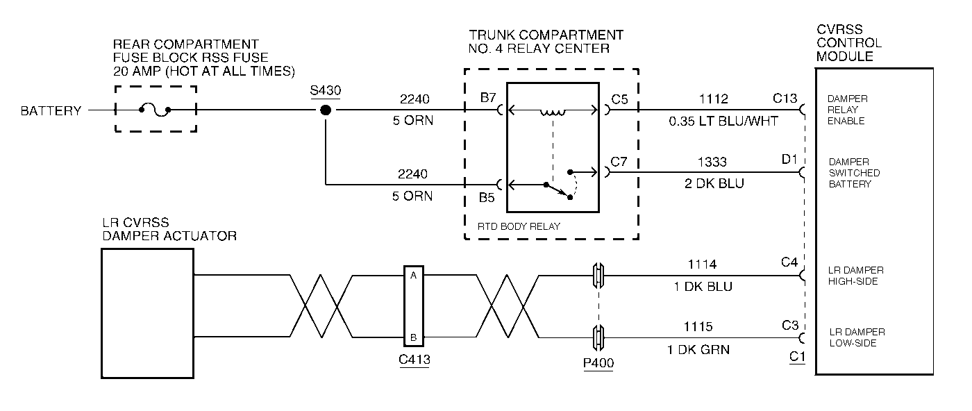
Circuit Description
The LR damper actuator is driven by the CVRSS control module via a method known as Pulse-Width Modulation (PWM). Battery voltage is PWMed (switched on and off) at a high frequency (2.0 kHz), thus, controlling the amount of current delivered to the actuator. By controlling the amount of current to the actuator, the CVRSS control module can then control the damping force in the damper. A higher level of damping force is achieved by providing correspondingly higher current levels, relating to higher percentages of PWM duty cycle.
The default damper state (with no battery voltage, and thus no current, provided to the attached actuator) is one that provides a minimum damping force.
Conditions for Setting the DTC
The DTC is set when the CVRSS control module measures an ON-state feedback voltage greater than a preset fault threshold during a damper diagnostic test procedure.
The DTC is set when the CVRSS control module performs a test procedure on each damper actuator approximately every 16 seconds. During this test procedure the damper actuator is briefly energized (ON-state test) and de-energized (OFF-state test). If, twice consecutively, the feedback voltage during the ON-state test is above the fault threshold, the corresponding DTC is set.
The DTC turns HISTORY when the CVRSS control module no longer senses a short to battery voltage condition on the damper low-side drive.
Action Taken When the DTC Sets
| • | The LR damper actuator will be disabled by commanding 0 % PWM duty cycle. The LR corner of the vehicle will be soft. |
| • | The SERVICE RIDE CONTROL message will be displayed. |
Conditions for Clearing the MIL/DTC
| • | Use the scan tool. |
| • | Use the On-Board diagnostic CLEAR RSS CODES feature. |
Test Description
Important:
• Do not backprobe the sensors, actuators, or any sealed connectors. • When all the diagnostics and repairs are complete, clear the DTCs
and verify the operation.
The number(s) below refer to the step number(s) on the diagnostic table.
-
This step checks for an internal short circuit condition in the actuator.
-
This step checks for a short to voltage condition on the actuator pigtail harness.
-
This step checks the CVRSS actuator harness for a short to voltage condition with the actuator disconnected. If voltage is indicated, there is short to voltage condition on CKT 1115.
-
This step checks the CVRSS actuator harness for a short circuit condition between CKT 1114 and CKT 1115.
Step | Action | Value(s) | Yes | No |
|---|---|---|---|---|
1 | Was the CVRSS System Check performed? | -- | Go to Step 2 | |
Is the measurement within the specified values? | 9.5-15.5 ohms | Go to Step 3 | Go to Step 8 | |
Is the measurement greater than the specified value? | 10 V | Go to Step 8 | Go to Step 4 | |
Is the measurement greater than the specified value? | 10 V | Go to Step 9 | Go to Step 5 | |
Check for a short circuit condition (continuity) between CKTs 1114 and 1115 (harness side). Was a short circuit condition found? | -- | Go to Step 6 | Go to Step 7 | |
6 | Repair the open circuit condition between CKTs 1114 and 1115. Is the repair complete? | -- | -- | |
7 |
Is DTC C1720 set? | -- | Go to Step 10 | |
8 | Replace the LR damper. Refer to Shock Absorber Replacement . Is the replacement complete? | -- | -- | |
9 | Repair the short to voltage condition in CKT 1115. Is the repair complete? | -- | -- | |
10 |
Important: The controller must be calibrated. Is the CVRSS control module calibrated? | -- | -- |
