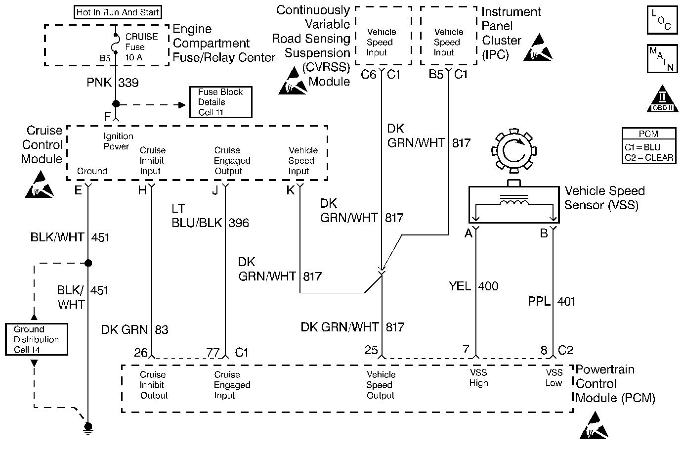
Circuit Description
The PCM contains chips called Output Driver Modules that provide 7 switchable ground outputs for operating solenoids, relays, telltales, and other devices. Each of these ground outputs has an internal fault line that feeds back to the PCM's microprocessor. When the output is OFF, the output driver should receive the 12 volts fed to the solenoid, relay, etc. When the output is ON, it should receive 0 volt since it is grounding the output. If it receives 0 volt when the output is OFF or 12 volts when the output is ON, it sets the fault line low. DTC P1642 is used to monitor the fault line of the vehicle speed output signal circuit. The Instrument Panel Cluster sends 12 volts on the vehicle speed output circuit to the PCM. The PCM then sends a pulse width modulated signal that the IPC, cruise control module and the RSS or CVRSS module use to determine vehicle speed.
Conditions for Running the DTC
| • | DTC P1640 not set. |
| • | Engine running at least 10 seconds. |
Conditions for Setting the DTC
Fault line is low for 2 seconds.
Action Taken When the DTC Sets
| • | The Malfunction Indicator Lamp (MIL) will not illuminate. |
| • | No message will be displayed. |
Conditions for Clearing the DTC
| • | A History DTC will clear after forty consecutive warm-up cycles with no failures of any non-emission related diagnostic test. |
| • | A Last Test Failed (current) DTC will clear when the diagnostic runs and does not fail. |
| • | Use a scan tool to clear DTCs. |
| • | Interrupting PCM battery voltage may or may not clear DTCs. This practice is not recommended. Refer to Powertrain Control Module Description . |
Diagnostic Aids
Reviewing the Failure Rec. may help diagnose an intermittent failure by showing how long ago and under what conditions the DTC set.
Test Description
Number(s) below refer to the step number(s) on the Diagnostic Table.
-
With the key ON and the vehicle not moving, 0 volts should be received at the PCM displaying OK.
-
By creating a vehicle speed signal a open/short can be observed, if present. If a fault is present it will only be displayed on the scan tool intermittently due to the pulse width modulated signal.
Step | Action | Value(s) | Yes | No |
|---|---|---|---|---|
1 | Did you perform the Powertrain On-Board Diagnostic (OBD) System Check? | -- | Go to Step 2 | |
Does the display indicate OK? | -- | Go to Step 3 | Go to Step 6 | |
Does the display EVER indicate Open/Short? | -- | Go to Step 4 | Fault not present. Refer to Diagnostic Aids | |
4 |
Is the voltage the same or more than the value specified? | 10.0 volts | Go to Step 7 | Go to Step 5 |
5 | Repair the open or short to ground on the Vehicle Speed Output circuit. Is the repair complete? | -- | Go to Powertrain Control Module Diagnosis for Verify Repair | -- |
6 | Repair the short to voltage on the Vehicle Speed Output circuit. Is the repair complete? | -- | Go to Powertrain Control Module Diagnosis for Verify Repair | -- |
7 |
Was the terminal contact repaired? | -- | Go to Powertrain Control Module Diagnosis for Verify Repair | Go to Step 8 |
8 | Replace the PCM. Refer to Powertrain Control Module Replacement/Programming . Is the replacement complete? | -- | Go to Powertrain Control Module Diagnosis for Verify Repair | -- |
