Tools Required
| • | J 28410 Gasket
Scraper (Aluminum Components) |
Visual Inspection Procedure
- Inspect the cylinder head for the following:
| • | Cracks, damage or pitting in the combustion chambers . |
| • | Scoring of the camshaft bearings and/or the journals. If the camshaft
bearing journals appear to be scored or damaged, you must replace the cylinder
head. DO NOT machine the camshaft bearing journals |
| • | Debris in the oil galleries. Continue to clean the galleries until
all debris is removed. |
| • | Coolant leaks or damage to the deck face sealing surface. If coolant
leaks are present, measure the surface warpage as described under Cylinder
Head Resurfacing. |
| • | Damage to any gasket surfaces |
| • | Damage to any threaded bolt holes |
| • | Burnt or eroded areas in the combustion chamber |
| • | Cracks in the exhaust ports and combustion chambers |
| • | External cracks in the water chamber |
| • | Restrictions in the intake or exhaust passages |
| • | Restrictions in the cooling system passages |
| • | Rusted, damaged, or leaking core plugs |
- If the cylinder head is cracked or damaged, it must be replaced.
No welding or patching of the cylinder head is recommended.
Cleaning Procedure
| • | Clean all cylinder head surfaces with non-corrosive solvent. |
| • | Blow out all the oil galleries using compressed air. |
| • | Remove any carbon deposits from the combustion chambers using
the J 8358
. |
| • | Clean any debris or build-up from the lifter pockets. |
| • | Inspect the cylinder head again for the items noted under Visual
Inspection. |
Flatness Measurement Procedure

- Clean any remaining head
gasket material from the cylinder head face using the J 28410
.
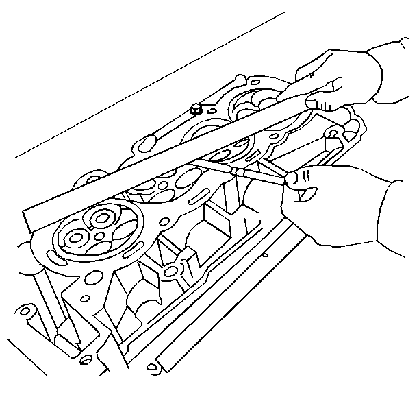
- Place a straight-edge diagonally across the cylinder head face
surface.
- Measure the clearance between the straight-edge and the cylinder
head using a feeler gage at four points along the straight-edge.
| • | If warpage is less than 0.05 mm (0.002 in), the
cylinder head surface does not require resurfacing. |
| • | If the warpage is between 0.05 mm and 0.2 mm (0.002 in
and 0.008 in), you must resurface the head. |

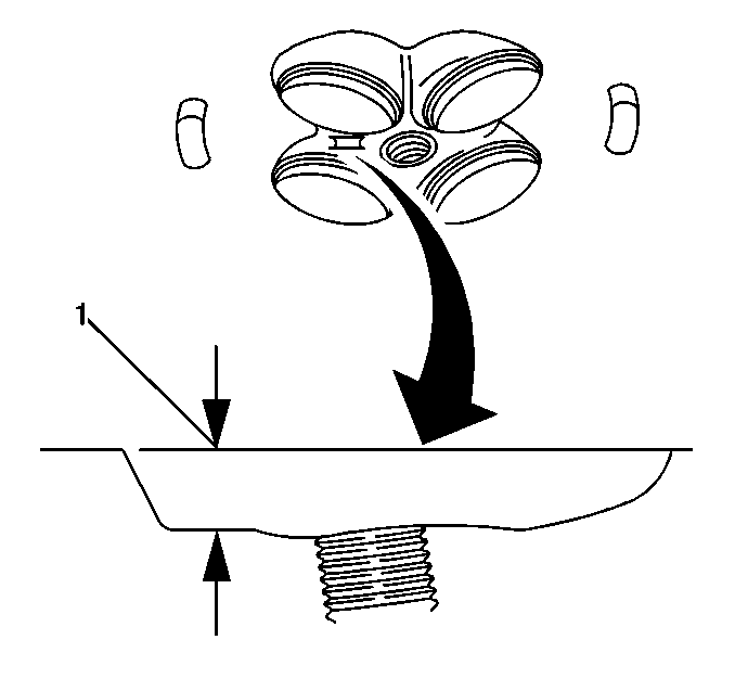
- If resurfacing is required,
the dimension between the combustion chamber gauge pad and the deck surface
(1) must be at least 10.5 mm (0.413 in).
Valve Guide Measurement Procedure

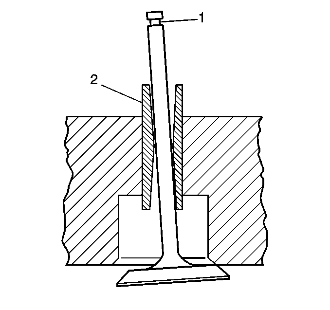
- Measure the valve stem(1)-to-guide(2)
clearance as follows:
| • | Excessive valve stem-to-guide clearance may cause an excessive
oil consumption and may also case a valve to break. Insufficient clearance
will result in noisy and sticky functioning of the valve and will disturb
the engine assembly smoothness. |
| • | Clamp the J 8001
to the cylinder head at the camshaft cover rail. |
| • | Locate the dial indicator so that the movement of the valve stem
from side to side (crossways to the cylinder head) will cause a direct movement
of the indicator stem. |
| • | The dial indicator stem must contact the side of the valve stem just
above the valve guide. |
| • | Drop the valve head about 1.6 mm (0.0064 in) off
the valve seat. |
| • | Use light pressure when moving the valve stem from side to side
in order to obtain a clearance reading. |
- If the clearance for the intake valve is greater than 0.11 mm
(0.0045 in) and a new standard diameter valve stem will not bring the
clearance within specifications, the cylinder head must be replaced.
- If the clearance for the exhaust valve is greater than 0.12 mm
(0.005 in) and a new standard diameter valve stem will not bring the
clearance within specifications, the cylinder head must be replaced.
- Valve guide wear at the bottom 10 mm (0.39 in) of
the valve guide is not significant to normal operation.


