Exhaust Manifold Replacement Left Manifold
Removal Procedure
Tools Required
J 28467-A Engine Support Fixture
- Remove the radiator cradle beauty panel.
- Remove the air cleaner assembly. Refer to Air Cleaner Assembly Replacement in Engine Controls.
- Remove the left and right engine torque struts. Position the struts out of the way.
- Remove the engine cooling fans. Refer to Engine Cooling Fan Replacement in Engine Cooling.
- Install the J 28467-A .
- Raise the vehicle on the hoist.
- Remove the two nuts securing the motor mount to the engine cradle.
- Remove the two bolts securing the motor mount bracket to the crankcase.
- Remove the two bolts securing the motor mount bracket to the cylinder head.
- Remove the two nuts securing the motor mount to the mount bracket.
- Remove the four nuts securing the Exhaust Manifold Rear Pipe to the converter. Reposition the converter out of the way with a support or a strap.
- Lower the vehicle.
- Raise the engine by adjusting the engine support fixture.
- Remove the motor mount and the bracket.
- Raise the vehicle.
- Remove the four bolts securing the rear generator bracket.
- Remove the two bolts at the manifold outlet flange.
- Disconnect the oxygen sensor wire.
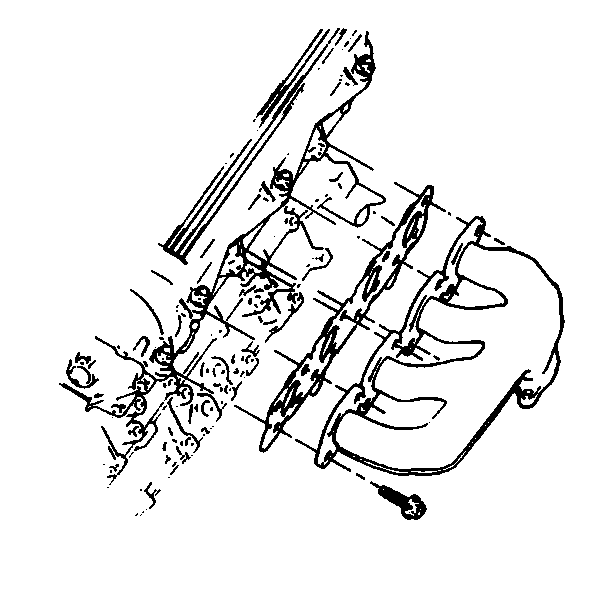
- Remove the exhaust manifold bolts.
- Remove the manifold and the gasket. Discard the gasket.
- Remove the oxygen sensor if replacement is necessary. Refer to Heated Oxygen Sensor Replacement in Engine Controls.


Installation Procedure
- Install the exhaust manifold by inserting the outlet pipe partially into the exhaust crossover pipe.
- Move the manifold into position.
- Install the gasket to the manifold. Hold the gasket in position by inserting two bolts.
- Start the remainder of the manifold bolts.
- Coat the oxygen sensor threads with high-temperature anti-seize, P/N 5613695 or equivalent.
- Install the sensor.
- Connect the exhaust oxygen sensor.
- Install the rear generator bracket.
- Position the motor mount and the bracket.
- Loosely install two nuts securing the mount to the bracket.
- Lower the vehicle.
- Loosely install two bolts to the mount bracket at the cylinder head.
- Lower the engine to the installed position guiding the motor mount studs in the cradle holes.
- Raise the vehicle. Refer to Lifting and Jacking the Vehicle in General Information.
- Loosely install two nuts to the bottom of the motor mount.
- Loosely install two bolts securing the mount bracket to the crankcase.
- Install the rear generator bracket.
- Install four nuts at the converter to the exhaust manifold rear pipe.
- Lower the vehicle.
- Remove the J 28467-A .
- Install the engine cooling fans. Refer to Engine Cooling Fan Replacement in Engine Cooling.
- Install the air cleaner assembly. Refer to Air Cleaner Assembly Replacement in Engine Controls.
- Install the left and right engine torque struts. Refer to Engine Mount Replacement .
- Install the radiator cradle beauty cover.

Notice: Use the correct fastener in the correct location. Replacement fasteners must be the correct part number for that application. Fasteners requiring replacement or fasteners requiring the use of thread locking compound or sealant are identified in the service procedure. Do not use paints, lubricants, or corrosion inhibitors on fasteners or fastener joint surfaces unless specified. These coatings affect fastener torque and joint clamping force and may damage the fastener. Use the correct tightening sequence and specifications when installing fasteners in order to avoid damage to parts and systems.
Tighten
Tighten the bolts to 25 N·m (18 lb ft).

Tighten
Tighten the nut to 40 N·m (30 lb ft).
Tighten
Tighten the crankcase bolts to 60 N·m (44 lb ft).
| • | Tighten the generator bolts to 30 N·m (22 lb ft). |
Tighten
Tighten the fasteners in steps 12, 17 and 18 to 30 N·m
(22 lb ft).
Tighten
Tighten the four screws to 50 N·m (37 lb ft).
Tighten
Tighten the bolts to 25 N·m (18 lb ft).
Tighten
Tighten the fasteners installed in step 14 to 30 N·m (22 lb ft).
Exhaust Manifold Replacement Right Manifold
Removal Procedure
- Remove the rear oxygen sensors at the back edge of the right cam cover and the rear pipe. Refer to Heated Oxygen Sensor Replacement in Engine Controls.
- Disconnect the harness clip.
- Raise the vehicle on the hoist. Refer to Lifting and Jacking the Vehicle in General Information.
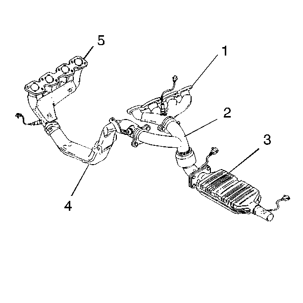
- Remove the exhaust manifold rear pipe (2) from the front of the catalytic converter.
- Remove the suspension position sensor at the lower control arm from both sides.
- Remove or disconnect the intermediate shaft, as necessary, from the steering gear.
- Support the rear cross member of the engine cradle with a tall screw jack.
- Remove the four cradle-to-body bolts.
- Lower the rear of the engine cradle.
- Remove the four bolts securing the Exhaust Manifold Rear Pipe to the exhaust manifold and crossover exhaust pipe.
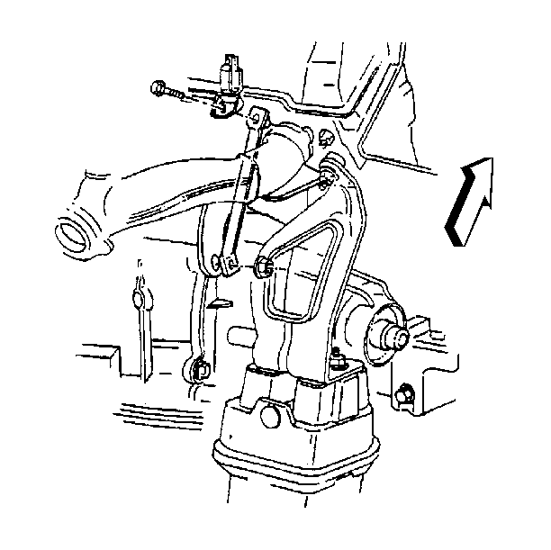
- Remove the right side cylinder head to the transaxle brace.
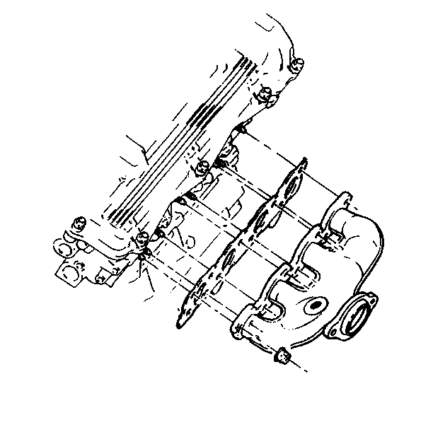
- Remove the exhaust manifold nuts. Some nuts may require removal with an open end wrench or universal coupling tools.
- Remove the manifold and the gasket. Discard the gasket.
- Remove the oxygen sensor. Refer to Heated Oxygen Sensor Replacement in Engine Controls.


Installation Procedure
- Coat the oxygen sensor threads with high temperature anti-seize, GM P/N 5613695 or equivalent.
- Install the oxygen sensor.
- Install the manifold gasket over the cylinder head studs.
- Install the manifold and the nuts.
- Install the right side cylinder head to the transaxle brace.
- Install the exhaust manifold rear pipe (2) and secure with four bolts. New bolts are recommended for maximum joint integrity.
- Raise the engine cradle into position.
- Connect the intermediate shaft to the steering gear.
- Connect the exhaust manifold rear pipe to the catalytic converter with four nuts.
- Connect the suspension position sensors to the lower control arms.
- Lower the vehicle.
- Connect the oxygen sensor. Refer to Heated Oxygen Sensor Replacement in Engine Controls.
- Install the harness retainer.
Notice: Use the correct fastener in the correct location. Replacement fasteners must be the correct part number for that application. Fasteners requiring replacement or fasteners requiring the use of thread locking compound or sealant are identified in the service procedure. Do not use paints, lubricants, or corrosion inhibitors on fasteners or fastener joint surfaces unless specified. These coatings affect fastener torque and joint clamping force and may damage the fastener. Use the correct tightening sequence and specifications when installing fasteners in order to avoid damage to parts and systems.
Tighten
Tighten the sensor to 40 N·m (30 lb ft).

Tighten
Tighten the nuts to 25 N·m (18 lb ft).

Tighten
Tighten the bolt and nut to 50 N·m (37 lb ft).

Tighten
| • | Tighten the M8 bolts to 25 N·m (18 lb ft). |
| • | Tighten the M10 bolts to 40 N·m (30 lb ft). |
Tighten
Tighten the four bolts to 100 N·m (74 lb ft).
Tighten
Tighten the bolt to 50 N·m (37 lb ft).
Important: When correctly aligned the flanges for the converter and the exhaust manifold rear pipe are parallel. If this condition does not exist, realign the Exhaust Manifold Rear Pipe by loosening the exhaust manifold bolts and repositioning the exhaust manifold rear pipe.
Tighten
Tighten the nuts to 25 N·m (18 lb ft).
