Tools Required
Removal Procedure
Notice: Do Not attempt to repair the EVAP pipes or the connecting hoses. Replace
the damaged EVAP pipes or the connecting hoses are damaged. If the nylon EVAP
pipe becomes kinked and cannot be straightened, it must be replaced.

- Relieve fuel system pressure.
Refer to
Fuel Pressure Relief
.
- Raise the vehicle. Refer to
Lifting and Jacking the Vehicle
in
general information.
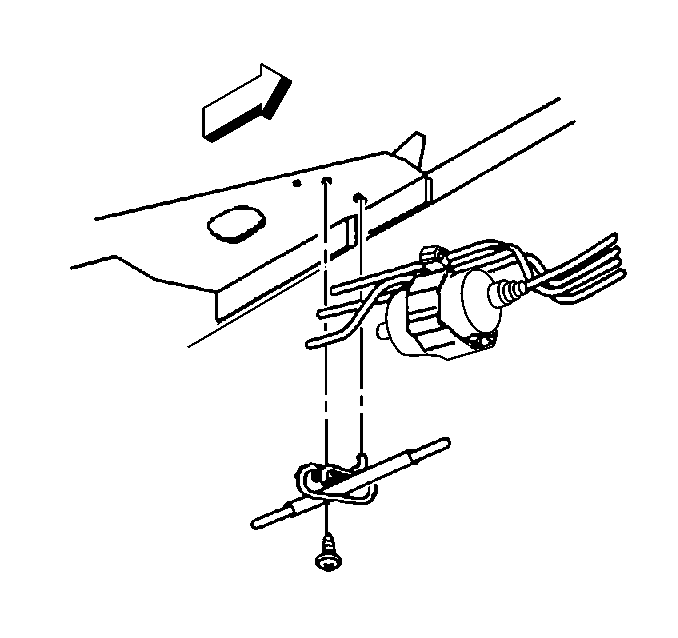
- Remove retaining hardware for the section to be replaced.
- Inspect the location of the attaching hardware for installation.
- Remove the fuel pipe retainer.
- Disconnect the quick connect fittings at the fuel vapor pipe (1),
fuel return (3), or fuel feed pipe (2). Refer to
Metal Collar Quick Connect Fitting Service
.
- Install the protective caps on pipe.

- Remove the quick connect
fitting at the fuel filter.
- Remove the hardware retaining section of the pipe to be replaced.
- Note the location of the attaching hardware for installation.
- Remove the section of pipe to be replaced.
- Wipe off the male pipe end using a clean shop towel.
- Inspect quick-connect fittings for dirt and burrs.
Notice: Use an emery cloth in order to remove rust or burrs from the fuel pipe.
Use a radial motion with the fuel pipe end in order to prevent damage to the
O-ring sealing surface.
- Clean or replace components or assemblies as required.
Installation Procedure
Caution: In order to reduce the risk of fire and personal injury observe the
following items:
| • | Replace all nylon fuel pipes that are nicked, scratched or damaged
during installation, do not attempt to repair the sections of the nylon fuel
pipes |
| • | Do not hammer directly on the fuel harness body clips when installing
new fuel pipes. Damage to the nylon pipes may result in a fuel leak. |
| • | Always cover nylon vapor pipes with a wet towel before using a
torch near them. Also, never expose the vehicle to temperatures higher than
115°C (239°F) for more than one hour, or more than 90°C (194°F)
for any extended period. |
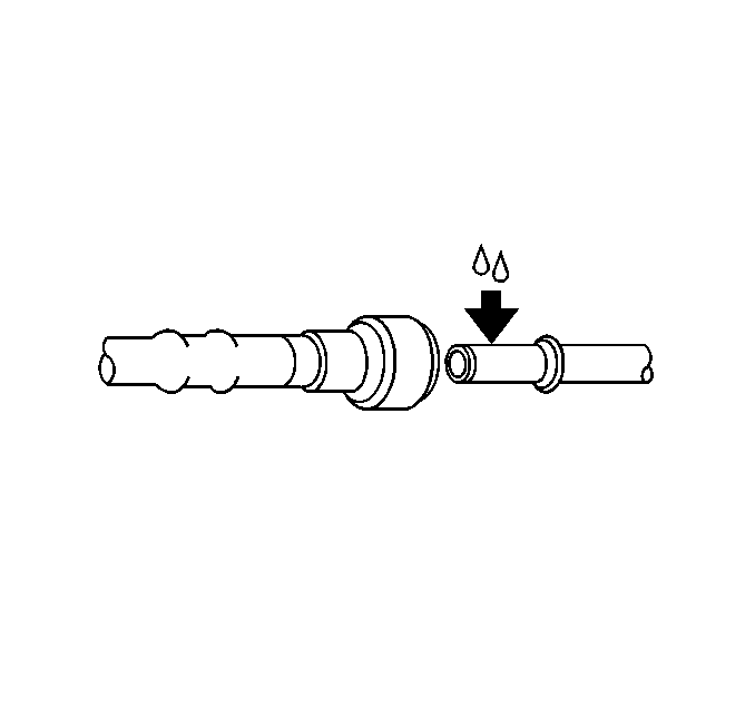
| • | Apply a few drops of clean engine oil to the male pipe ends before
connecting fuel pipe fittings. This will ensure proper reconnection and prevent
a possible fuel leak. (During normal operation, the O-rings located in the
female connector will swell and may prevent proper reconnection if not lubricated.) |

- Position the new fuel
pipe in original location.
- Remove the protective cap(s) from fuel pipe(s).

- Apply a few drops of clean
engine oil to the male connector pipe end.

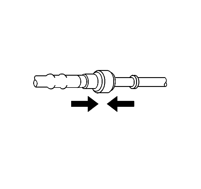
- Connect the quick-connect
fitting at fuel filter.
- Push connector together to cause the retaining tabs/fingers to
snap into place.

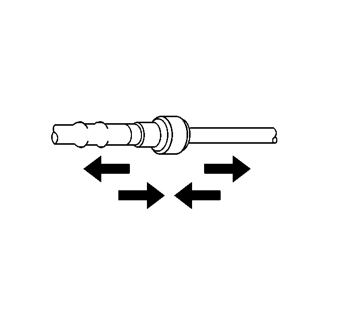
- Pull on both ends of connection
to make sure connection is secure once installed.
- Reinstall retaining hardware.
- Reinstall the fuel pipe retainers.
- Lower the vehicle.

- Reinstall the for engine
compartment fuel pipes at the fuel vapor pipe (1), fuel return (3),
or fuel feed pipe (2). Refer to
Metal Collar Quick Connect Fitting Service
.

- Tighten the fuel filler
cap.
- Connect the negative battery cable. Refer to
Caution: Unless directed otherwise, the ignition and start switch must be in the OFF or LOCK position, and all electrical loads must be OFF before servicing
any electrical component. Disconnect the negative battery cable to prevent an electrical spark should a tool or equipment come in contact with an exposed electrical terminal. Failure to follow these precautions may result in personal injury and/or damage to
the vehicle or its components.
.
- Inspect for leaks.
| 13.1. | Turn the ignition switch ON for 2 seconds. |
| 13.2. | Turn the ignition switch OFF for 10 seconds. |
| 13.3. | Turn the ignition switch ON. |
| 13.4. | Check for fuel leaks. |
- Reinstall the intake manifold sight shield. Refer to
Intake Manifold Removal
in engine mechanical.


